Find the best antennas for TV, radio, and wireless. Compare top antenna deals, use free antenna calculators, follow DIY guides, and buy high-performance antennas with confidence.
3 Volt Car Adapter
Electroscope
Source : Elektor Circuit
Electronic Stethoscope Circuit
*40X amplification based on comparison of analog versus electronically assisted amplified listening with maximum volume at the peak frequency(125 Hz). Check it Out !
Digital TV Antenna
Digital antenna TV has to have capable reception on TV Band Digital TV frequency , from 470-862 MHz.
We can design with Yagi model, Logarithmic antenna Design , Fractal Antenna design or other design that proven can receive with good quality on this band. with frequency reception, we can design this :
862 - 470 = 392 , 1/2 Lambda will be , 490 + 392/2 = 666 Mhz
For Yagi antenna , I use calculation design from K7MEM.com
Ads Link
or you can also get design from Su and Chang http://www.jpier.org/PIERL/pierl12/14.09102302.pdf
The implementation looks like this :
I have tried the Su and Chang design , with good reception at Digital Terrestrial TV Channel and average quality in analog TV channel reception.
DIN rail ARM7 Ethernet/USB Subsystem (LPC2138)
- This package is ideal for industrial use, facilitating quick connection and relocation
- DIN rail mountable and compatible with OKW Railtec C-5 enclosure
- On-board BASIC compiler runs 30 times faster than interpreted BASIC
SUCCESS
These were then programmed to acquire and stream the accelero- meter data to a Linux server. The server would save and graph the data in real time. When an 'image jump' was recorded, this accelero-
meter data was analyzed to help identify the faulty mechanism.
University of Hawaii
APPLICATIONS
- Ethernet
- Wireless
- Sensors
- Monitoring
TECHNICAL SPECIFICATIONS
System
- DIN rail enclosed 60 MHz 32 bit ARM7 CPU (LPC2138)
- Programmable in a compiled BASIC, C, HTML and XML
- On-board BASIC compiler runs 30 times faster than interpreted BASIC
- 1 million I/O operations per second
Size
- 88.5mm x 84mm (3.4” x 3.3”)
- Compatible with DIN rail OKW Railtec C-5 enclosure
Storage
- 512k flash with 64k user code space
- 224k available for user web pages
- 224k user file space
- 32k RAM
Power
- Less than 1W
- 5-40V DC input
- Output power 3.3V regulated, 250 mA available to user
Connectors
- 25 pins programmable for I/O
- 8 x 10 bit analog A/Ds, 1 10bit DAC
- Optional USB connection
Data Logger 200 MHz (LPC4330)
- Dual ARM CPUs
- SDcard Flash file system
- 83 inputs and outputs
- 4 UARTs with DMA support
- 2 I2S with DMA support
- 2 CAN controllers
- Flexible GPIO interrupts
- 8 timers
- Motor PWM
- Quadrature encoder
- 2 USBs
- Ethernet MAC
- Flexible serial GPIO capable of camera/display
- optional RTC with battery backup
SUCCESS
The robots all use your Super Pro board. Your boards connect with the Android tablets via Bluetooth.
www.stupidfunclub.com
APPLICATIONS
- Sensors
- Monitoring
- Measurement
- Logging
- Simple controls
TECHNICAL SPECIFICATIONS
System
- 200 MHz ARM Dual Core M4/FPU M0+ CPU
- Floating point hardware accelerator
- Programmable in a compiled BASIC or C
- Operates faster than 50 million BASIC lines/second
Size
- 3.2” x 2.05”
Storage
- 264K RAM
- 8MB flash
- micro SDcard socket
Power
- 5V DC input
Connectors
- Arduino-shield compatible
- Serial Debug connector
- JTAG connector
- Connections for 83 digital I/O
- 8 x 10bit analog A/Ds, 1 10bit DAC
- Programming dongle sold separately
LPC54102 Dual Core (LPC54102 100 MHz)
- Twice as many processors
- Sixteen times the memory of competitors
- Sixteen times the RAM of competitors
- 46 inputs and outputs
SUCCESS
The robots all use your Super Pro board. Your boards connect with the Android tablets via Bluetooth.
www.stupidfunclub.com
APPLICATIONS
- Sensors
- Monitoring
- Measurement
- Logging
- Simple controls
TECHNICAL SPECIFICATIONS
System
- Board-mounted dual core 100 MHz ARM M4 with Floating Point Accelerator
- Second 100 MHz ARM M0 core (LPC54102)
- Programmable in a compiled BASIC or C
- Operates faster than 24 million BASIC lines/second
Size
- 2.1” x 2.05”
Storage
- 484k user code space (40,000 Instructions)
- 64k user data
- 104k RAM
- 512k flash
Power
- 5V DC input
Connectors
- Debug connector
- Connections for 46 digital I/O
- 11 x 12 bit analog A/Ds, 1 10bit DAC
- Programming dongle sold separately
SUPER-PRO Board 100 MHz (LPC1756)
SUPER-PRO Board 100 MHz (LPC1756) – Build a Powerful ARM Cortex-M3 Development Board at Home
The SUPER-PRO Board 100 MHz (LPC1756) is a high-performance ARM Cortex-M3 development board that can be constructed as a Do It Yourself (DIY) electronics project at home. Powered by the NXP LPC1756 microcontroller, this board is capable of handling demanding embedded applications such as IoT systems, robotics, industrial controllers, SDR peripherals, and real-time data acquisition.
In this comprehensive guide, you will learn how to design, build, and use a 100 MHz microcontroller development board using commonly available components. This article is written for makers, engineers, students, and electronics hobbyists who want a professional-grade embedded platform without paying the high cost of commercial boards.
Why the LPC1756 Is Ideal for DIY Embedded Projects
The NXP LPC1756 belongs to the LPC1700 family of ARM Cortex-M3 microcontrollers and operates at clock speeds up to 100 MHz. It offers a powerful balance between performance, power consumption, and peripheral integration, making it a favorite for industrial and commercial designs.
Key Advantages
- 100 MHz ARM Cortex-M3 core
- 512 KB Flash memory
- 64 KB SRAM
- USB 2.0 Full Speed device/host
- Ethernet MAC
- Multiple UART, SPI, I2C interfaces
- CAN bus support
Because of this rich feature set, the LPC1756 is widely used in automation controllers, data loggers, industrial gateways, and IoT edge devices.
What Is the SUPER-PRO Board?
The SUPER-PRO Board is a DIY-friendly development platform designed around the LPC1756 microcontroller. Unlike commercial boards, this design emphasizes:
- Easy home construction
- Through-hole + SMD hybrid assembly
- Expandable headers
- Professional signal integrity
This makes it an excellent choice for learning advanced embedded system design while still remaining affordable.
Board Architecture Overview
The SUPER-PRO Board is built around several functional blocks:
- Core microcontroller unit (LPC1756)
- Clock generation (main crystal + RTC crystal)
- Power regulation (5V to 3.3V)
- Programming & debugging interface
- Peripheral expansion headers
Each block can be tested independently, which greatly simplifies troubleshooting during home construction.
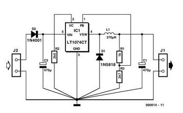
Power Supply Design
The LPC1756 operates at 3.3V, but most hobby power sources provide 5V (USB adapters, bench supplies, power banks). A stable and low-noise power supply is critical for reliable operation at 100 MHz.
Recommended Power Components
- 5V input (USB or DC jack)
- Low-dropout 3.3V regulator (AMS1117-3.3 or equivalent)
- Bulk electrolytic capacitors
- High-frequency ceramic decoupling capacitors
Good power filtering improves ADC accuracy, USB stability, and Ethernet performance.
Clock Circuit – Achieving Stable 100 MHz Operation
The LPC1756 requires an external crystal oscillator for accurate timing. A typical configuration uses:
- 12 MHz main crystal
- 32.768 kHz RTC crystal (optional)
Using the internal PLL, the microcontroller multiplies the crystal frequency to achieve the full 100 MHz system clock.
Proper PCB layout and short trace lengths are essential to avoid clock instability.
Programming and Debugging Interface
To program the SUPER-PRO Board, you can use either:
- ISP bootloader via UART
- JTAG/SWD debugger
For beginners, the built-in NXP ISP bootloader is the easiest method. Advanced users will prefer JTAG or SWD for real-time debugging.
Peripheral Expansion and GPIO Access
One of the strongest advantages of the SUPER-PRO Board is its expandability. All major GPIO ports are routed to pin headers.
Supported Interfaces
- UART (Serial communication)
- SPI (Displays, sensors, memory)
- I2C (RTC, EEPROM, sensors)
- CAN bus (Automotive & industrial)
- Ethernet (via external PHY)
This allows the board to be used in a wide range of real-world applications.
DIY PCB Fabrication Options
You can build the SUPER-PRO Board using:
- Home-etched PCB (for experienced builders)
- Low-cost PCB fabrication services
- Prototype perfboard (limited performance)
For best results at 100 MHz, a professionally manufactured PCB is recommended.
Component List (Affiliate-Optimized)
Core Components
-
NXP LPC1756 Microcontroller
👉 Buy on Amazon | Shopee | Tokopedia -
12 MHz Crystal Oscillator
👉 Amazon -
AMS1117-3.3 Voltage Regulator
👉 Amazon
Development & Debugging Tools
-
USB-to-UART Adapter
👉 Buy on Amazon -
JTAG/SWD Debugger
👉 Buy on Amazon
Software Development Environment
The LPC1756 is supported by several professional-grade development environments:
- MCUXpresso IDE
- Keil MDK-ARM
- GCC + OpenOCD
MCUXpresso is recommended for beginners due to its free license and integrated tools.
Practical DIY Applications
Once completed, the SUPER-PRO Board can be used in:
- IoT gateways
- Industrial monitoring systems
- Robotics controllers
- Home automation hubs
- Educational ARM training kits
This versatility makes it a long-term investment rather than a single-use project.
Conclusion
Building the SUPER-PRO Board 100 MHz (LPC1756) at home is a powerful way to learn professional embedded system design. It combines high performance, flexibility, and affordability into a single DIY project.
Whether you are an engineering student, hobbyist, or product developer, this board provides a solid foundation for advanced microcontroller applications.
PRO Board 60 MHz (LPC2103)
SUCCESS

By orienting the design around the Pro, I can make changes in the device’s operation quickly in software rather than making hardware design changes, which is a much slower process.
Measuretech
APPLICATIONS

- Sensors
- Monitoring
- Measurement
- Logging
- Simple controls
TECHNICAL SPECIFICATIONS

System
- Board-mounted 60 MHz ARM7 CPU (LPC2103)
- Programmable in a compiled BASIC or C
- Operates faster than 10 million BASIC lines/second
Size
- 2.1”x2.05”
Storage
- 20k user code space (1600 Instructions)
- 5k user data
- 32k flash size
- 8k RAM size
Power
- <250 mW
- 5-7V DC input
- Provides 500 mA +5V
Connectors
- Debug connector
- Connections for 21 digital I/O
- 6 x 10 bit analog A/Ds
- Programming dongle sold separately
PRO-Plus Board 100 MHz (LPC1751)

- More than doubles the processing speed of the PRO-Start.
- Twice the number of I/O connections of the PRO.
SUCCESS

Selecting our Arduino Shield-compatible MPUs for its work, the team created a successful prototype that they scaled and deployed across the company’s fleet of vehicles.
APPLICATIONS

- Sensors
- Monitoring
- Measurement
- Logging
- Simple controls
TECHNICAL SPECIFICATIONS

System
- Board-mounted 100 MHz ARM M3 CPU (LPC1751)
- Programmable in a compiled BASIC or C
- Operates faster than 24 million BASIC lines/second
Size
- 2.1” x 2.05”
Storage
- 20k user code space (1600 Instructions)
- 5k user data
- 32k flash size
- 8k RAM size
Power
- 350 mW
- 5-7V DC input
Connectors
- Debug connector
- Connections for 52 digital I/O
- 4 x 12 bit analog A/Ds
- Programming dongle sold separately


