Antenna Handbook

Transmission Lines

CONDUITS FOR TRANSPORTING RF SIGNALS between elements of a system. For example, transmission lines are used between anexciter output and transmitter input, and between the transmitter input and its out-put, and between the transmitter output and the antenna. Although often erro-neously characterized as a “length of shielded wire,” transmission lines are actuallycomplex networks containing the equivalent of all the three basic electrical compo-nents: resistance, capacitance, and inductance. Because of this fact,
transmissionlines must be analyzed in terms of an RLC network. 

Parallel and coaxial lines
 
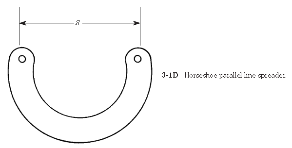
This article will consider several types of transmission lines. Both step-functionand sine-wave ac responses will be studied. Because the subject is both conceptualand analytical, both analogy and mathematical approaches to the theory of trans-mission lines will be used.Figure 3-1 shows several basic types of transmission line. Perhaps the oldest andsimplest form is the parallel lineshown in Figs. 3-1A through 3-1D. Figure 3-1A shows an end view of the parallel conductor transmission line. The two conductors,of diameter d, are separated by a dielectric (which might be air) by a spacing S.These designations will be used in calculations later. Figure 3-1B shows a type ofparallel line called twin lead. This is the old-fashioned television antenna transmis-sion line. It consists of a pair of parallel conductors separated by a plastic dielectric.TV-type twin lead has a characteristic impedance of 300 , while certain radio trans-mitting-antenna twin lead has an impedance of 450 . Another form of twin lead isopen line, shown in Fig. 3-1C. In this case, the wire conductors are separated by anair dielectric, with support provided by stiff (usually ceramic) insulators. A tie wire(only one shown) is used to fasten each insulator end to the main conductor. Someusers of open line prefer the form of insulator or supporter shown in Fig. 3-1D. 


This form of insulator is made of either plastic or ceramic, and is in the form of a U. Thepurpose of this shape is to reduce losses, especially in rainy weather, by increasingthe leakage currents path relative to spacing S.Parallel lines have been used at VLF, MW, and HF frequencies for decades. Evenantennas into the low VHF are often found using parallel lines. The higher imped-ance of these lines (relative to coaxial cable) yields lower loss in high-power appli-cations. For years, the VHF, UHF, and microwave application of parallel lines waslimited to educational laboratories, where they are well suited to performing exper-iments (to about 2 GHz) with simple, low-cost instruments. Today, however, printedcircuit and hybrid semiconductor packaging has given parallel lines a new lease onlife, if not an overwhelming market presence.Figure 3-1E shows a form of parallel line called shielded twin lead. This type of lineuses the same form of construction as TV-type twin lead, but it also has a braided shield-ing surrounding it. This feature makes it less susceptible to noise and other problems.The second form of transmission line, which finds considerable application atmicrowave frequencies, is coaxial cable(Figs. 3-1F through 3-1L). This form ofline consists of two cylindrical conductors sharing the same axis (hence “coaxial”),and separated by a dielectric (Fig. 3-1F). For low frequencies (in flexible cables)the dielectric may be polyethylene or polyethylene foam, but at higher frequenciesTeflonand other materials are used. Also used, in some applications, are dry air anddry nitrogen.

 Several forms of coaxial line are available. Flexible coaxial cable is perhaps themost common form. The outer conductor in such cable is made of either braid or foil(Fig. 3-1G). Television broadcast receiver antennas provide an example of such cablefrom common experience. Another form of flexible or semiflexible coaxial line is heli-cal line(Fig. 3-1H) in which the outer conductor is spiral wound.Hardline(Fig.3-1I) is coaxial cable that uses a thin-wall pipe as the outer conductor. Some hardlinecoax used at microwave frequencies has a rigid outer conductor and a solid dielectric.Gas-filled lineis a special case of hardline that is hollow (Fig. 3-1J), the centerconductor is supported by a series of thin ceramic or Teflon insulators. The dielec-tric is either anhydrous (i.e., dry) nitrogen or some other inert gas.Some flexible microwave coaxial cable uses a solid “air-articulated” dielectric(Fig. 3-1K), in which the inner insulator is not continuous around the center con-ductor, but rather is ridged. Reduced dielectric losses increase the usefulness of the
cable at higher frequencies. Double-shielded coaxial cable (Fig. 3-1L) provides anextra measure of protection against radiation from the line, and EMI from outsidesources, from getting into the system.Stripline, also called microstripline(Fig. 3-1M), is a form of transmission lineused at high UHF and microwave frequencies. The stripline consists of a criticallysized conductor over a ground-plane conductor, and separated from it by a dielec-tric. Some striplines are sandwiched between two groundplanes and are separatedfrom each by a dielectric.


(from  Practical Antenna Handbook by Joseph J Carr)

Broadband TV Antenna Chireix-Mesny

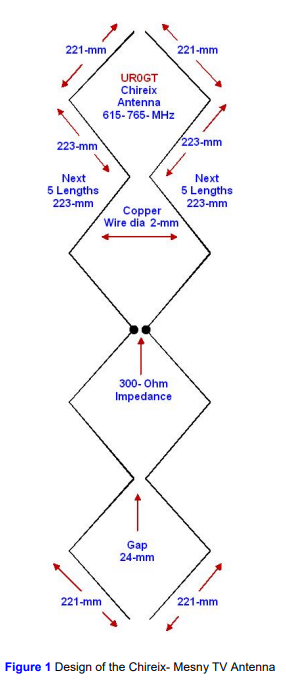
The simple broadband TV antenna works at the 615- 765- MHz. Antenna has input impedance 300- Ohm at the pass band. Antenna may be used with antenna amplifier that has such input impedance. The antenna is a variant of the famous Chireix- Mesny Antenna. Antenna may be used with coaxial cable with broadband transformer. switched to the TV 150- MHz. 

Figure 1 shows design of the antenna. 


Figure 2 shows impedance of the antenna (antenna placed at 7- meter above the real ground). Figure 3 shows SWR of the antenna (antenna placed at 7- meter above the real ground). Figure 4 shows DD of the antenna (antenna placed at 7- meter above the real ground). The MMANA model of the Chireix- Mesny TV Antenna may be loaded: http: // www.antentop.org/018/chireix_018.htm Note I.G.: Chireix- Mesny Antenna was designed in France by Henri Chireix, Chief Engineer of the Societe Francaise Radiotelectrique, and Rene Mesny, Professor of Hydrography in the French Navy. Papers on the antenna were published (in different variations) in the 1926- 1928s. Patent H. Chireix: French Patent # 216,757, filed Mar. 10, 1926. Antenna originally was used for directive radiation and reception at short waves. Lately the antenna was widely used at VHF- UHF waves. 
(Source : Antentop)

Rhombic Antenna Transmitter for Distance Receiving of TV Antenna

Below it is described one of those antennas- it is a Rhombic Antenna. Rhombic Antenna is easy to make and at the same time has perfect parameters. Rhombic Antennas are easy to build and at the same time has high gain and good diagram directivity. However the antennas have some lack. Such antennas required lots space for installations and need at least for masts instead one that used to support traditional directional antennas. 


Figure 1 shows design of the Rhombic Antenna. Rhombic Antenna is a rhomb that hang up horizontally at the ground. Feeder is connected on to one sharp angle of the rhomb. Terminated resistor is connected on to far sharp angle of the rhomb. The resistor’s value should be equal to the impedance of the rhomb at the working frequencies of the antenna. As usual the value is near 700- Ohm. Working frequencies of the antenna may have pass band in hundreds megahertz. So using such matched resistor allows create a super broadband antenna that has impedance near 700- Ohm at the frequencies window in several hundred megahertz. High gain and high directivity of the rhomb antenna could be explained by combining gain and diagram directivity of the parts of the antenna. The antenna consists of four wires with traveling wave. 

Figure 2 shows the combination. Each wire has own gain and diagram directivity.

The gain and diagram directivity depends on ratio the length of the wire to the working wavelength. So, the summary gain and diagram directivity depends on the ratio the length of the wire to the working wavelength and to the sharp angle of the rhomb.


Table 1 shows data for Rhombic Antenna with different parameters. To keep such parameters antenna should be placed above the ground at height not less the 2- 3 wavelength of the working band of the antenna. Antenna may be fed by open ladder line with wave impedance 300… 600- Ohm. At this case the antenna could be matched at all working frequencies band. Antenna may be fed through a coaxial cable when two simple matching transformers are used. 


Figure 3 shows feeding Rhombic Antenna through a coaxial cable. First transformer is a broadband transformer made on two wire ladder line. It is two wires line with varying wave impedance on the length. The wave impedance of the line changes from 700- Ohm at rhomb side to 300- Ohm at coaxial cable side.At coaxial cable side the coaxial cable should not connect straight away to the line. Coaxial cable connected to the line through a symmetrical transformer 4:1 made on lengths of the used coaxial cable. The transformer makes symmetrical and provides matching of the Rhombic Antenna to coaxial cable. Loop of the coaxial cable should have electrical length lambda/2. To calculate such transformer you need to know the shortening coefficient of the used coaxial cable.

It is possible to use coaxial cable with any wave impedance- 50 or 75 Ohm. Matching impedance of the 4:1 transformer depends on the coaxial cable. At 50- Ohm cable it is got transformer 200:50- Ohm, at 75- Ohm cable it is got transformer 300:75- Ohm. Transformer 300:75- Ohm should have best matching result with open line transformer. There are lots link in the internet how the transformer may be calculated. 

One of them is:http://www.nlemma.com/calcs/dipole/balun.htm. When the coaxial cable symmetrical transformer is used the broadband of the antenna depends on the broadband of the transformer. As usual coaxial cable transformer has good matching at the 5% frequencies band calculated from the central working frequency of the transformer. So, when such transformer is used the broad band of the Rhombic Antenna is limited to pass band of the transformer. Antenna may be made from a strand wire in diameter 2… 3- mm. It may be copper, aluminum or bimetal (with copper or aluminum layer) wire. Terminated resistor at the antenna may be any small power noninductive resistor. This one should be protected from atmospheric influences.  (Source : Antentop)

Broadband TV Antenna Design

The simple broadband TV antenna works at the 580- 760- MHz. Passband of the antenna is 180- MHz. Antenna has input impedance 300- Ohm at the pass band. 
The Design also can modified from  Band frequency 470-806 and with impedance 50 Ohm.

Antenna may be used with antenna amplifier that has such input impedance. Antenna may be used with coaxial cable with broadband transformer. The antenna is critical to any nearby metal subjects. Place the antenna with isolator connected to Antenna body and tower or antenna holder.

They can destroy the DD of the antenna. Space in 50 cm near the antenna should be free from such metal or conductive subjects. If antenna is used for reception purposes the best way is place low noise amplifier at the antenna terminal. 
LNA or Low Noise Amplifier can be made with 2SC3358 or 2SC3355, Low Noise Wideband Amplifier 0 - 1 GHz


Figure 1 shows view of the antenna. Figure 2 shows design of the antenna. Figure 3 shows impedance of the antenna (antenna placed at 7- meter above the real ground). Figure 4 shows SWR of the antenna (antenna placed at 7- meter above the real ground). Figure 5 shows DD of the antenna (antenna placed at 7- meter above the real ground). The MMANA model of the Broadband TV Antenna may be loaded: http: // www.antentop.org/018/ur0gt_tv_018.htm (Source : Antentop with modification in content)

Digital TV Antenna Outdoor

According to frequency range of the Digital TV Outdoor Antenna :

For Band VHF : 170 MHZ - 230 MHZ, Which is  television channels 7–13 (VHF-Hi), known as "Band III" internationally. A number of DTV channels have begun broadcasting here, especially many of the stations which were assigned to these channels for previous analog operation.

Digital TV Antenna OutdoorThe U.S. FCC allocated television broadcasting to a channelized roster as early as 1938 with 19 channels. That changed three more times: in 1940 when Channel 19 was deleted and several channels changed frequencies, then in 1946 with television going from 18 channels to 13 channels, again with different frequencies, and finally in 1948 with the removal of Channel 1 (analog channels 2-13 remain as they were

For Band UHF : 470 MHZ - 860 MHZ

    Australia

  • UHF citizens band(Land mobile service): 476–477 MHz
  • Television broadcasting uses UHF channels between 503 and 694 MHz
  • Canada

  • United Kingdom
  • Currently channels 21–35, 37 and 39–60 are used for Freeview digital TV.[6] Channel 36 is used for radar; channel 38 was used for radio astronomy but has been cleared to allow PMSE users access on a licensed, shared basis.
  • 791–862 MHz,[7] i.e. channels 61–69 inclusive were previously used for licensed and shared wireless microphones (channel 69 only), has since been allocated to 4G cellular communications.
  • United States
  • 470–512 MHz: Low-band TV channels 14–20 (shared with public safety land mobile 2-way radio in 12 major metropolitan areas scheduled to relocate to 700 MHz band by 2023[11])
  • 512–608 MHz: Medium-band TV channels 21–36
  • 608–614 MHz: Channel 37 used for radio astronomy and wireless medical telemetry[12]
  • 614–698 MHz: Mobile broadband shared with TV channels 38–51 auctioned in April 2017. TV stations will relocate by 2020. 

Specification of this Digital TV Antena Outdoor :
  •  Easy To Install : : Need common Tools set and Ladder if you have no access to roof , cabling path is easy to set , follow your house space wall.
    Digital TV Antenna Outdoor Mounting Installation at Roof House
  
What Purchaser said about this Antenna  ?


This Antenna Digital very Excellent for Outdoor use. You assembled the antenna by hand using the enclosed directions, easy no tools needed. Powered and tested the rotation/motor of the antenna in the house, worked as expected (didn’t use the remote as I didn’t have batteries, used the dock). Grabbed my ladder and tools with additional wood screws and washers as the package only contained 2 wood screws (not enough if you ask me). Climbed on to my roof and mounted the bracket on the side of my chimney tunnel exit than mounted the assembled antenna with pole. Ran the antenna’s coaxial cable down the side of my house and used a flat coaxial jumper cable to get it through my window seal into my house as I did not want to drill through my wall. Once I plugged in a second coaxial from the window flat jumper cable inside my house to the antenna power box and a third coaxial cable from the power box to my TV, I was in business... I troubleshooted the antenna rotation using our favorite channel that used to be fuzzy and studdered until I got great reception. The great news... once our favorite channel was in perfect reception, I used the settings on my TV to auto save all view able channels and now I have a TOTAL OF 54 CHANNELS (we live in Belton MO) that my family and I can watch!! That’s a win if you ask me. We had under 10 channels that stuttered before with our typical indoor antenna. Now to see how far it holds up and see how well it works during bad weather like rain and snow, not so sure if the material would hold up in Arizona sun but will be willing to try when we move back.

Another Purchaser commented :
I have tried many antennas, trying to get a TV station my wife wanted, and finally found it. Great antenna, easy to put together. I had a problem with the control box, but the customer service was great. I was very impress how quickly customer service answered all my questions and made sure I was happy with my purchase. I can receive 102 channels that is 2x more than all the other antennas I have tried. I even tried an antenna that cost about $200.00 bucks and this antenna is 2x better. I like that the antenna comes complete. Coax, pole. control box, remote. No extra wire is needed for the rotate function. Assembly is easy the antenna snaps together. Im a very picky guy, and do not normally give 5 stars, but this one really deserves it. I give the antenna a 5 star and the customer service was fantastic it also gets a 5 stars.


Not Sattisfied Purchaser commented about this Antenna :
 The service department was excellent. Quickly answered my email. We did some troubleshooting which did not correct the problem, so they sent me a new upgraded model at no extra charge. So far it is working fine. I would recommend bc if there is a problem the service team will take care of it promptly.
Original problem
WA 2608 150 mile range antenna. I have had my antenna hooked up 6 days. Assembly was easy. Installation instructions were clear. However after I installed it and used compass points to aim it, I ran a scan I did not pick up channels 65 miles away (per antenna point app and antennaweb), I did however get 29 channels from closer towers. Tried running scans at different times of the day and night to see if that effected anything bc a few of the channels would go in and out while watching a program. Then it just quit picking up any channels at all. Tried multiple scans but got zero channels. Emailing Service Team.

The Very Best Indoor HDTV Antenna for your home

The Best Indoor HDTV Antenna - A streaming channels such as netflix, iflix, apple tv, upstream, all of which are paid monthly channels that charge our monthly fees. With this The Best Indoor HDTV Antenna for your home, you can get free channels without extra monthly fees. 
Never Pay your cable or satellite for television again ! No Monthly Fees, No Increases and No Contracts. No more triple-digit monthly bills! A One time purchase for less than 30$ can save you 80-212$ every month, adding up to 960-2544$ a year! This innovative Indoor flat Digital Antenna is worth every cent you pay. You can Get All local Channels in Crystal Clear HD Quality !
Depending on your location, , the HDTV antenna can receive include NBC, FOX, CBS, ABC, PBS, THE CW, QUBO, TELEMUNDO, UNIVISION, RTV, THIS TV, ION, ME TV, TV Showss, News, sitcoms, kids programs, sports, the weather channels and So much more.

Our Pick

Easy Installation Indoor Antenna
Easy Plug and Play Indoor Antenna , out of the way, you can choose the installation position the antenna - on the table, wall or window (strongly recommended).
The compact design plugs directly into 'ANT IN' port and can tuck neatly behind your TV . Easily move TV Antenna between TVs at home or away so your content travels with you. For Home or Apartment, Camping, Yacht and Store/Office.
The U Must Have Amplified HD Digital TV Antenna comes with HD Crystal-Clear 4K Ultra HD and 1080 Full HD & HD Sound Quality.  Powerful Amplifier Signal and Low Noise Filter outs of Cellular and FM signals resulting in clearer picture
Hang the indoor antenna on a window or wall, or better position where owns better reception of your House. Note: Always remember re-scan for channels after moving the Antenna. Visit - "dtv gov maps" information is useful.

Runner Up

Indoor Smart Switch Amplifier Signal Booster
Gesobyte Amplified HD Digital TV Antenna


The Gesobyte Amplified HD Digital TV Antenna come with smart switch control powerful amplifier signal booster next generation & crystal clear filter technology : filter out cellular and fm signals resulting in clearer picture and low noise, enhanced gain, range and frequency performance. Access to more free broadcast TV signals. 

Budget Pick 

1 By One Amplified HD Digital TV Antenna

Built-in high quality state-of-the-art nanotechnology
1 By One Amplified HD Digital TV Antenna
1 By One Amplified HD Digital TV Antenna 

Easy to Install, Lighweight and simple design, beautiful design, you can hide it behind the TV sets, or hang it on the window wall. 
With the nanotechnology for maximum strength increases the  long range reception capacity of the TV Antenna .


Best Long Range Outdoor HDTV Antenna

Best Long Range Outdoor HDTV Antenna as shows by Amazon , with range antenna coverage from 60 miles-150 miles , extremely high performance for Digital HDTV UHF Band.
Available with amplifier signal , 360 degree motorized , and wireless remote control.

150 Miles Range | Receive free digital broadcast High Definition TV signals Full HDTV Support: 720p, 1080i, 1080p Working Frequency: VHF 40~300MHz | UHF 470~890MHz Weather resistant - Watch Your Favorite Channels For Free Including Events Such As The FIFA World Cup, Olympic Games & Much More. Includes wireless remote controller and antenna pole mount
Channels: 1~69 Impedance: 75Ohm Max Output Level:105dB u V Main Voltage: AC-110V/60Hz Operation Temperature: -10° C ~ 50° C Coaxial Cable Length: 40' Dimensions: 18.1" X 3.5" X 11" 

Why 50 Ohm Impedance cable Ideal for Transmitting RF Signals ?

Inspired by Rodrigo , one of this blog reader, who ask about why used 50 Ohm impedance ?

The answer can be shown in the graph above. This was produced by two
researchers, Lloyd Espenscheid and Herman Affel, working for Bell Labs
in 1929.


They were going to send RF signals (4 MHz) for hundred of miles
carrying a thousand telephone calls. They needed a cable that would
carry high voltage and high power. In the graph below, you can see the
ideal rating for each. For high voltage, the perfect impedance is 60
ohms. For high power, the perfect impedance is 30 ohms.


This means, clearly, that there is NO perfect impedance to do both.
What they ended up with was a compromise number, and that number was 50
ohms.


You will note that 50 ohms is closer to 60 than it is to 30, and that is
because voltage is the factor that will kill your cable. Just ask any
transmitter engineer. They talk about VSWR, voltage standing wave ratio,
all the time. If their coax blows up, it is voltage that is the
culprit.


So why not 60 ohms? Just look at the power handling at 60 ohms -
below 50%. It is horrible! At the compromise value of 50 ohms, the power
has improved a little. So 50 ohm cables are intended to be used to
carry power and voltage, like the output of a transmitter. If you have a
small signal, like video, or receive antenna signals, the graph above
shows that the lowest loss or attenuation is 75 ohms.


Still, I get a lot of feedback from people who use 50 ohms for small
signals; you can see above that they are taking a 2-3 dB hit in
attenuation. Excuses I hear are “It's too late to change now!” or “That's the impedance of the box itself.”

This is especially true of most test gear, which is universally 50
ohms. You have to buy a matching network to use it at 75 ohms or any
other impedance. But there are lots of applications where 50 ohms is the
best choice.

( Source : Belden.com)

8 Bit RS-232 D/O Card

For you who wants to experiment with the early computer technology 8 bit Data , this project is very useful to start with, and 8 Bit Data Digital I/O still use in Industrial process , such on factories process control system.

Your old computer still can be use for this experiment, IBM PC XT or AT is fine with Processor 80x86.


And with BASIC computer programming Install, or QBASIC programming . Can Also programming by Turbo Pascal language.   The Circuit Consists Of IC CMOS 4040 , IC 74HC573 & 74HC541 and IC ULN2803.
The Parts lists shown at component lists.

The Design of This Digital Output card is based on accessing PC UART as shown at table2. The basic lines for UART communications is TXD and RXD for Transmit Data and Receive Data. The other lines are DTR, RTS, CTS, DCR, DCD and RI , each for input and output in communication 8 Bit Data via Serial Communication.
The Output voltage level on Serial port RS-232 are represent by +12 V for logic "1" and -12 V for logic "0".
The Connector K1 connected to serial port computer and the output through R1-D1 and R2-D2 and R3-D3 for TXD, DTR and RTS. IC6, IC7, IC8 are optocouplers are safe driving by R1-D1 , R2-D2 and R3-D3 for On/Off transistor inside it , when the voltage +12 V and -12V.  The optocoupler will saturate the transistor if the voltage goes to +12 V and goes to cut off the transistor when voltage goes to -12 V.
The RST and CLK drive 12 bit binary counter, and only 8 bit used . The LEN pulse used to hold latch output from IC2. And IC3 drive LED D4-D11 for shown logic state of DO card.

Computer have four terminal Serial Port ( COM1..COM4) as at table 1 , where each serial port , occupied 8 memory map location. as shown table . The Eight Open Collector Output form IC ULN2803A is final stage of this card, and can apply for switching up to 50V with the total output current not more than 500 mA.

The card can powered from regulate power supply from 9-15 V. On the next article I will show you how to program UART PC.

The PCB for DO Card and the component places.(Souces : Elektor Electronic)

Wideband Active Loop Antenna for Shortwave band general purpose receivers

Active Wide band Loop Antenna for 10-30 MHz Band shortwave band you can construct in your home as Do It Yourself Project (Source article : Elektor Electronics Magazine).

Parts List :

PCB Design and component place :


Loop Antenna is a good indoor antenna alternative for a long wire antenna.


Half Dipole Antenna for TV Reception you can build

I got this design from Antentop.org with title Unusual TV Antenna , is from Magazine 1966 . This antenna design as Tiny Antenna, this antenna can receive for 4 channel at that time, maybe more channel today.
TV station located far about 55 km and 105 km from TV reception.
The Antenna design itself is Dipole Antenna, half of dipole copper rod with 6mm diameter ( 3-AWG), with plastic tube about 36 mm ( 1 1/2 inch) is placed. The tube is filled by Iron sawdust, the length of the plastic is about 2/3 from the length of copper rod. shows in fig 1. for cable TV , you can use 75 Ohm or 50 Ohm impedance


DIY SWR Meter


Extremely Low Frequency Reciever using Arduino


Using Arduino Uno and ADC module, this circuit can pick up ELF Signal

Car Radio Alarm Circuit


Car Lights Monitor


Brake Lights Alarm Monitor for Car


source : Elektor

Bicycle Lights and Alarm

source : Elektor electronic

Car Alarm


Source : Elektor Electronic

Car Fuse Monitor


Source : Elektor Electronic

Nicad Charger Circuit


Source : Elektor Electronic

Lead Acid Battery Charger


Source : Elektor Electronic

Metal Pipe Detector Circuit

This circuit is useful for trace Metal Pipe Water and Gas.

Metal Detector Circuit with 9 Volt battery


This circuit from 303 Circuit Elektor Electronics . The LC circuit frequency will change when the metal object altered the Inductance of inductor.