There are many brands of antennas on the market, all of them promise good quality. This makes us need to determine what parameters help us to choose the right antenna, recommended according to the parameters of a good antenna
Impedance
Pick 75 Ohm input Antenna , meaning , the input Antenna matched with Coaxial 75 Ohm cable Impedance for TV , as Theory this will make the TV signal transmit/receive ideally100 % without reflected.
Range
Scientific fact: The Earth is round. (Sorry, flat-earthers.) The curvature of the Earth will block most over-the-air broadcast signals at roughly 70 miles. According to the current laws of physics, it is generally impossible to deliver the 100 and 150-mile range claims some antenna manufacturers boast.
Gain
Indicates how well the antenna focuses energy from a particular direction, in comparison with a standard reference antenna (an antenna with known performance, used to calibrate other or developing antenna technologies). The gain number specified on an antenna is the value in the direction of maximum reception intensity. Example Antenna Gain 6 dB, 9 dB, 14 dB, 18 dB. the greater the antenna gain (in dB) the better the reception
What this means is that the distance measured for an antenna's reception capacity is based on the hypothetical instance where the broadcast transmitters you're trying to receive signals from all line up like points on a single straight line. Also, it is relevant to note that "gain" in this usage doesn't take into account possible dips in reception from what is called "impedance mismatch". In practice, the antenna's performance can be faulty if its impedance is different from that of the cable connected to it.
Model
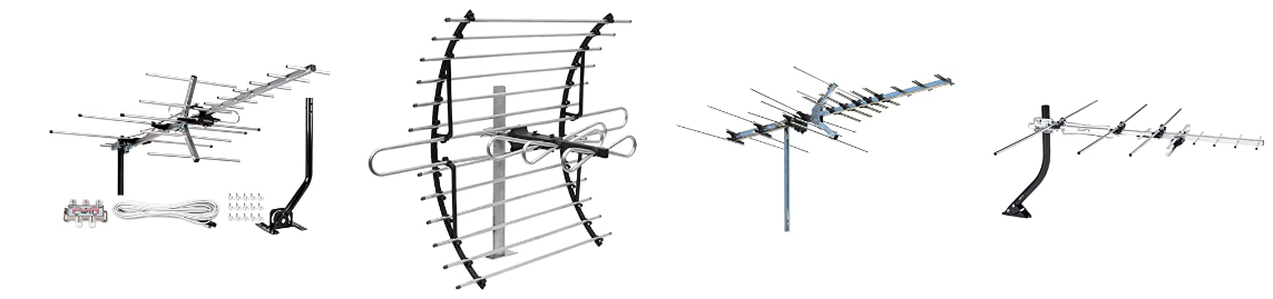
Antenna model consist of by range criteria Short Range/Medium Range/Long Range, by location installed Indoor/Outdoor/Attic Antenna , by frequency working UHF and UHF/VHF Antenna and by Style , Wireless , Unidirectional (Directional) and Multidirectional (Omnidirectional) Antenna
A Short-range digital TV antennas are engineered for distances within 50 miles of the broadcast towers. Their shorter range means they are very powerful and will consistently pick up your local signals.
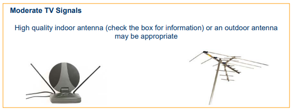
A Medium-range TV antennas are engineered for distances within 60 miles of the broadcast towers. These high-performance digital antennas can be placed on a tabletop or a wall. For optimal performance and to minimize interference from electronic devices in the home, place the antenna near a window or on a wall facing the broadcast towers. Outdoor HD antennas will perform best when installed in your attic, or preferably on a rooftop or fascia.
A Long-range HD antennas reach further than most other outdoor TV antennas and minimize interference from obstacles such as trees or heavy foliage, providing you with the best possible reception in every scenario.
Indoor Antenna , indoor TV antennas are designed with timeless features to blend into sophisticated spaces. These indoor antennas can be painted to match your wall, furniture, or accent color for a custom fit.
Outdoor TV Antennas , Perfect for suburban and rural areas, outdoor TV antennas are the best option overall for receiving long-range signals when installed on a roof or fascia, providing the best line-of-sight to the broadcast towers.
Attic TV Antennas, Installing your antenna in an attic allows you to conceal your antenna when an outdoor antenna is not possible. Our attic TV antennas provide powerful, long-range performance for consistent, reliable reception in the city and in rural areas.
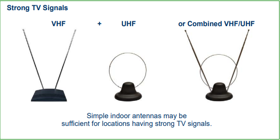
UHF Antennas, UHF HDTV antennas have the power and efficiency normally found in antennas up to 10 times their size. TV antenna designs are engineered to receive consistent high-gain across the entire UHF TV spectrum. UHF signals are broadcast on channels 14 to 69 and have a higher noise level and greater attenuation, so high-gain digital antennas are often required.
UHF/VHF Antennas, Over-the-air channels are divided into two bands, UHF and VHF. High-VHF signals are broadcast on channels 7 to 13 and UHF signals are broadcast on channels 14 to 69. UHF/VHF HDTV antennas represent a breakthrough in long-range performance. They are engineered to be smaller and more powerful across today's DTV spectrum, with dedicated UHF and VHF multi-directional elements that deliver range and reception in less-than-ideal locations

Filter
Some Antenna products , included this filter, the main function is to Blocks 4G/5G LTE cellphone and transmitter frequencies that cause pixelation and reception disruption.
How to Get the Best Reception Antenna ?
The actual receivable range may largely depend on your location and distance. Areas with large obstacles, such as terrain, high concrete buildings, trees, valleys or mountains will reduce the effective range.
Also keep away from the high power device that will make interference when you install the antenna.
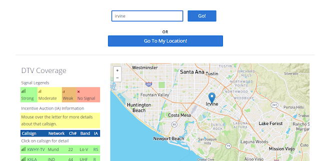
Use Transmitter Locator Software or other software related, will allow you to view the TV transmitters in your area. Using this tool, you will see the radius patterns showing
For example Enter your City name or ZIP Code and Click “Go” or Click “Go To My Locations” for Get DTV Coverage
Please note:
These predictions are based on a terrain-sensitive propagation model resembling but not identical to the propagation model used when calculating service and interference contours for licensed broadcast television stations. Actual signal strength may vary based on a variety of factors, including, but not limited to, building construction, neighboring buildings and trees, weather, and specific reception hardware. Your signal strength may be significantly lower in extremely hilly areas. Click on a callsign for details about that station's Incentive Auction repacking plans.
Antenna Range False Claim
Antenna products in market claims have the receive signal more than 100, 150, 200 miles, this is not true. We here to educate this false claims, there is no such antenna like that.
The truth is TV antenna reception is influenced by the shape of the earth's curvature.
That's why TV stations need a lot of relay stations, to cover places that are far from TV tower stations such as rural areas, valleys behind mountains, and so on.
Curvature of Earth per mile
How large is the curvature of Earth, then? As we don't notice it in our everyday lives, it has to be relatively small. Most sources consider 8 inches per mile as the most accurate estimate. That means that for every mile between you and an object, the curvature will obstruct 8 inches of the object's height.

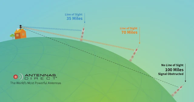
Scientific fact: The Earth is round. (Sorry, flat-earthers.) The curvature of the Earth will block most over-the-air broadcast signals at roughly 70 miles. According to the current laws of physics, it is generally impossible to deliver the 100 and 150-mile range claims some antenna manufacturers boast. While you may receive signals from farther away in absolutely ideal conditions (a home atop a hill whose broadcast towers are directly on top of another hill with a clear shot between the two and absolutely no obstacles) or you’re inclined to engineer a unique (and probably dangerously tall) setup, then consistent, reliable reception of anything over 70 miles away should not be expected. Range can also be impacted by factors such as location, obstructions in the terrain around you, other buildings, the location of transmitters on the broadcast tower, and other variables
The Channels You'll Receive
You may be thinking that watching TV with an antenna will bring you back to the old days of antennas when only a handful of stations were available. Today, most areas in the United States broadcast 50+ channels over the air. Locations like Los Angeles have as many as 175 channels. We’re talking about over-the-air broadcast television channels -which are transmitted in Full HD 1080p and with 5.1 surround sound- you receive for FREE once you have a TV antenna. In addition to your local NBC, CBS, ABC, CW, and FOX affiliates, you’ll also find a wide variety of specialty programming available on these stations. So much content is available over-the-air that we like to call it “the new basic cable”. Keep in mind, these are network and local channels. You won't receive any pay-TV stations via a TV antenna, ever. We’ve seen antennas claiming this possibility, but it is 100% false. You will not receive ESPN, CNN, or any other such channel with a TV antenna. Period. That said, there are many new streaming options becoming available all the time which combine broadcast TV content with packages available for purchase to watch sports channels, pay-TV subscriptions, and more, all from one streamlined platform.
The 4k TV Antenna
As of writing this, OTA television is not yet broadcast to the general public in 4K. However, that doesn’t stop unscrupulous antenna companies from claiming that (only) their antennas will allow you to watch broadcast TV in 4K. The truth is, once 4K broadcast television becomes available, any antenna will be able to receive it. What you, the TV-watcher, will need in order to view OTA television in 4K is a device which will be capable of decoding the transmissions your antenna receives so that you’re able to watch your shows in the new 4K standard. This can be a TV or a designated TV tuner, for example, a set-top box. We believe that our ClearStream™ HDTV Antennas will deliver the best, most reliable picture quality we’ve always been known for when that day comes, which is why we indicate on our packaging that all our antennas are “4K-Ready”. Until then, 4K-quality picture has become available through mediums such as Blu-Ray® and certain streaming services, but broadcast television viewers will need to wait until the new standard of television arrives on local airwaves in the near future, to view over-the-air television in 4K.
If you’re still unsure or just need guidance choosing the right antenna for your needs, we are here to serve as your beacons of light for all antenna myths you may be grappling with. Our Midwest-based Connection Crew is available 7 days a week to answer questions and help you achieve the best possible over-the-air TV-viewing experience. They’ll help you pick the right antenna for your location, troubleshoot installation, conduct a free home signal analysis, and more. They’re a passionate bunch of real antenna enthusiasts who will help you separate fact from fiction and find success with a TV antenna.
Reference :
http://www.Antennasdirect.com
http://www.amazon.com
https://www.fcc.gov/media/engineering/dtvmaps
https://www.omnicalculator.com/physics/earth-curvature#curvature-of-earth-per-mile