Antenna Modeler and Optimizer using 4nec2 software

For antenna design model and optimize the design for analyse and calculate pattern and calculate Power of Receive and Transmit Power of antenna , I am using free and open source antenna modeler and optimizer 4nec2 from Arie Voors.
You can download in here http://www.qsl.net/4nec2/
or Download from my GDrive 
4nec2 support Windows operating systems and also Linux by installing Wine Software before installing 4nec2.
Feature from 4nec2 software : I get this from http://www.qsl.net/4nec2/ :

* Graphical 2D and 3D visualization of Far- and Near-field data and Geometry strutures (including circular polarization view).

 * Line-chart visualization for freq-sweep Gain, F/B, F/R, SWR and impedance data. * Drag and drop style Geometry Editor to assist the starting antenne modeller.

* Full Nec2 and Nec4 command support, including GX, GM, GR, GA, GH and surface patches.
* Capable of running up to 11000 wires and/or segments (limited by the max of 2Gb of windows on-board memory)

* Support for inclusion of surface-wave component in far-field data. * 3D geometry display for surface patches included.

* Variable substitution included for complete Nec2/4 command set enabling you to model by equation. * Sophisticated real-time 3D geometry and pattern viewer showing real wire-radius.

* AO-style gradient/hill-climbing optimizer included.

* Genetic Algorithms based optimizer included.

* Automatic variable sweeper with line-chart output.

 * Automatic convergence tester with line-chart output.

* Interactive Smith chart visualization for freq-sweeps.

* Integrated Sommerfeld ground calculations with frequency-sweep.

* Automatic generation of VOACAP propagation prediction type 13 and –14 antenna files.
* Automatic coversion of AO (*.ant)and EZnec (*.ez)input files.

 * ‘Insulated-Wire’ and 'LC-trap' loading-types included.

* Automatic conversion for feet, inch, #awg to meters and elevation/azimuth to phi/theta and reverse.

* Batch processing for automatic testing, calculation and/or conversion of multiple Nec, AO and/or EZnec input-files.

* Extensive segment- en geometry validation, such as: Intersecting volumes, Short/thick wires at sharp angle, Unequal segmentation for parallel wires, Too low hight, Large radius or length changes at junctions, etc.

 * Screen grabber for easy cut/paste, print or save parts of the screen, window or form. * Geometry builder to create cylindric, patch, plane, box, helix and parabola shaped structures using auto-segmentation and/or equal-area rules.

* Automatic generation of Stub-, L-, Pi- and Tee-matching-networks (low- and high-pass)

* Visualization of circular polarization components E(left) and E(right) for far-field. * EZnec style MiniNec ground included.

 * Capable of running the default Lawrence Livermore National Laboratories Nec4 engine.

* Running on all systems from early Windows-95 to latest Windows-Vista * More than 450 example files

* Context sensitive Help-file.

* Completely free.

 For tutorial 4nec2 you can get free on http://www.qsl.net/4nec2/Tutorial_4NEC2_english.pdf , I will also writing the tutorial for you with different example and different antenna design.

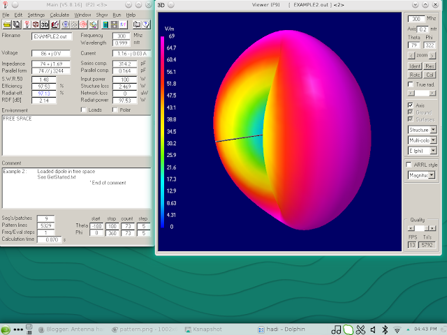
The example will talking about design 300 MHz antenna with SWR 1.48 , and wavelength 0.999 meter and input power antenna 100 Watt. See at the picture below from 4nec2 software :
  
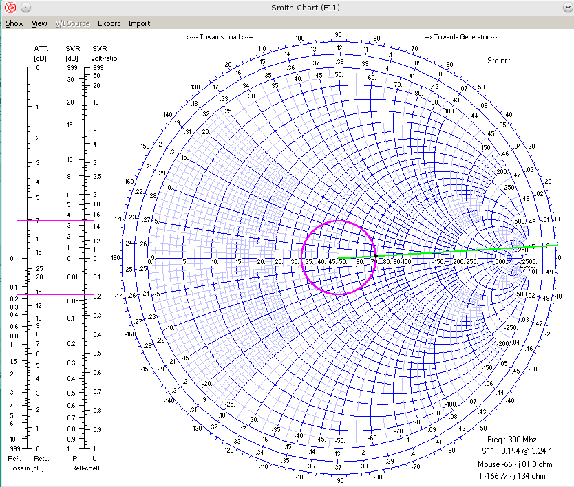
On The example we can get information about frequency 300 MHz, wavelength 0.999 meter , SWR 50 1.48 , efficiency 97.53 % , antenna wire on xyz position and we can also can see smith chart calculation 

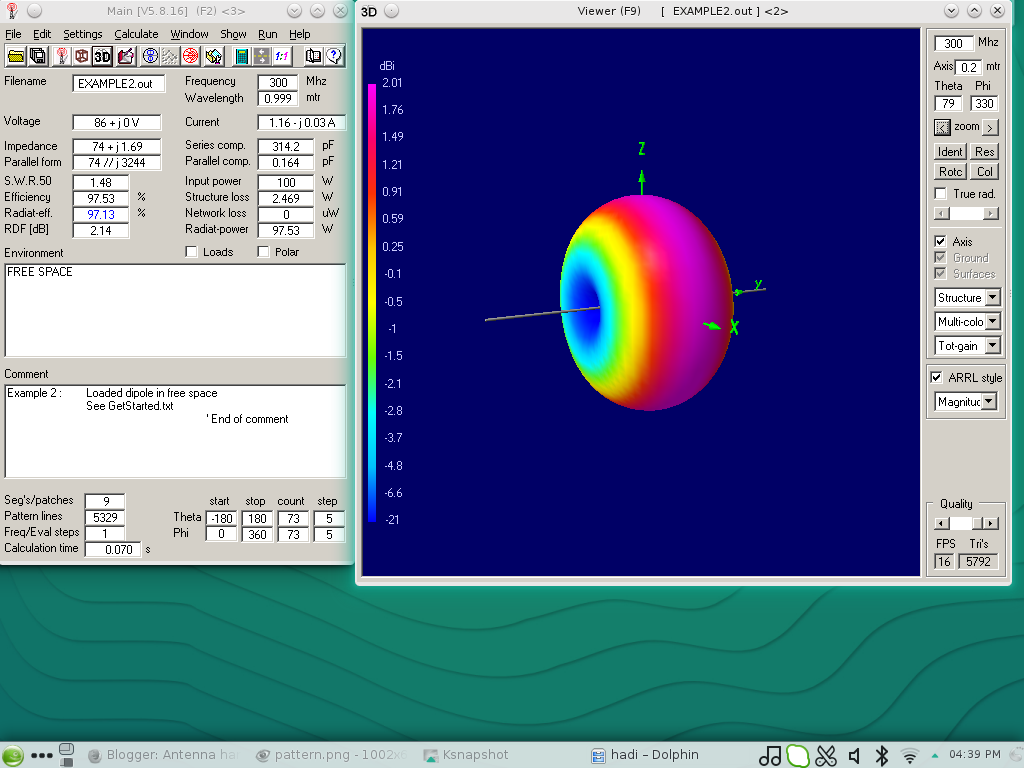
Antenna Pattern also can be view from the software :
And also 2D and 3D antenna simulation signal from antenna , can be calculate and view by this software :
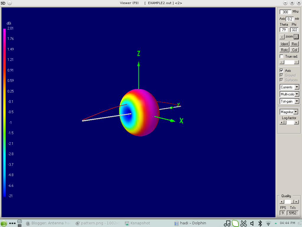

3D Zoom Mode

2D Mode View

Current Mode View

Vertical Gain View

Horizontal Gain View

Pattern Gain View

 Phi Theta View Gain

3D Sense View

Tilt Phase View

Transparent View

Vertical Gain View

How To Build SOHO Small Office Home Office with free software and small budget ?

The SOHO (Small Office Home Office) Design with 12- 20 Employee or user 


As in digital business era, small office or home office be required using computer and printer for easy correspondence inside and outside office to contact another company, or customer, making letter, report, and electronic mail etc.
This also required computer Network for sharing Printer and another Network Equipment for low cost.

As we know open sources is community of developer and provide many option of software that can be used for building small office or home office with small business that can reduce cost for providing Network in his/her office with quality same as, and more than  others software that must be paid.

For this reason it needs education for The office owner and IT Team , also employees who using this advantage of open source for daily activity in office.

For this purpose We will needs this material :

Computer / Desktop as Server 
Printer
Router
Modem
Notebook / Desktop with Wi-Fi card inside 

Software :

Ubuntu Linux  Operating System Server
Ubuntu Linux  Operating System/Chrome OS for desktop/notebook (Same function as Windows 10/8/7)
Libre Office or openoffice for Notebook and Desktop (same function as Microsoft Office)
Kmail (Same function as Microsoft Outlook )
Thunderbird/Mozilla as Browser
Many Opensource software you can maximize using it for start a small business or office with free of charge.

These all software you can get free of charge, the cost will appear on Computer , Printer, Wireless Router, Modem from ISP (Internet Service Provider), Monthly Internet Billing, and Notebook.

Implementation 


Download Ubuntu Linux Server here

Download Ubuntu Linux OS/Chrome OS for Desktop/Notebook


Notebook Lenovo Chromebook Flex 5 2-in-1 Laptop


Do not Throw your Old Computer

If still have an old computer PC with i386 Processor, maybe you can still used it and take advantage from this old computer with open source software.
You can install Unix Operating System such as FreeBSD Unix or Linux Operating System.

The hardware minimum system for Installing Free BSD is :

32bit x86 Intel Processor such i386, 80486 or higher CPU with minimum 64MB RAM or 128MB RAM with 1.5 GB hard drive memory.

amd64 Processor , inlcude AMD Athlon, AMD opteron , multi core Intel xeon, and Intel core 2.

While for Linux Operating System support Processor Intel 80386, 80486, Pentium, Pentium Pro, Pentium II, Pentium III CPU, these includes processors such 386SX, 486SX, 486DX, and 486DX2, included Cyrix Processor and AMD Processor.

The Advantage of Old computer is for small business industry and home small business owner , you can have low cost for software and hardware budget for running your business. You can email, browsing, also make spreadsheet calculation and financial plan and accounting also office function can be done with Libre Office , and printing also can be done. Simplify this, you can have your own business office with old computer and old printer, also you need router for connecting to Internet.

For Example I used Opensuse Linux for my notebook. So I do not have to worry about copyright issue software. Because all software that I need for working in home are open source such as Libre Office, KMail, etc.


This is capture from my notebook , I use opensuse for Operating System.

And for Using Printer, We use share printer in the home network. Although the Server we use still using Windows OS 7 , because it is not belong to me. But The Ideas of this plan is to reduce or minimize your SOHO or small business from taking his/her budget from capital for buying expensive system of small hone network computer. And you can still save your budget for other used.


And here it is how I setting my notebook connecting to Wireless printer outside of my room.

I am using Motorolla Modem, TPLink Router, Sony Vaio Notebook and PC Intel Computer  


4G LTE 4 Pole Inter Digital Filter for Digital TV


This is the design of 4G LTE filter for Digital TV . As we know some of 4G LTE transmit frequency , overlapping with Digital TV reception frequency on 698 - 806 MHz. So, this 4 Pole Inter digital Filter made from aluminium plate and copper rod. You can experiment with it , I am not tested yet, for another design you can follow from VK3UM software online at VK3UM.com

LM 335 Temperature Sensor Circuit

Temperature Control Circuit :

Image Courtesy Texas Instrument


The temperature controller circuit using +5 V voltage source from I/O slot at IBM PC/XT/AT.

IC LM 335 from Texas Instrument have the ability to detect temperature from ranging -40 celcius degree until 100 celcius degree.
This LM 335 from Texas Instrument , is zener diode which have the linear coefficient voltage increment related with increment of temperature with formula :

Vz = + 10 mV/ C (celcius degree) , with current opeartion between 400 uA until 5 mA.

On the circuit Resistor 2.2 K use for limit the current flow to cathode pin from LM 335 which is output of LM 335 sensor temperature.
On circuit Resistance of R is 2.2 K , and at 25 Celcius degree from data sheet of LM 335 , voltage at LM 335 will be 2.982 Volt , so current flow can be calculate :

Vcc = + 5 V
Voltage at 25 Celcius on LM 335 = 2.982 V
Voltage at Resistor R 2.2K is = 2.018 V
Current flow through LM 335 and R will be = 2.018 V / 2.2 K = 0.9 mA

This 0.9 mA current at LM 335 still on at range of sensor LM 335, and then the output cathode pin of LM 335 sensor from Texas Instrument connect to input 0 of ADC0809 Analog and Digital convertion data from Texas Instrument at pin 26.

Temperature Sensor LM 335 from Texas Instrument


Temperature Sensor using IC LM 335 from Texas Instrument. LM 335 is Zener Diode which sensitive of temperature change in it surrounding , which is reverse bias on it breakdown area with output :

Vz = [10 mV/Kelvin] …..........[2-1]

Because there is gap different 273 degree between Kelvin and Celcius , so the output in Celcius for LM 335 from Texas Instrument will be :

Vz = 2.73 Volt + [ 10 mV/Celcius] T.........[2-2]

where T is in Celcius Degree

IC LM 335 from Texas Instrument have temperature range between -40 celcius degree – 100 celcius degree

I use LM 335 in Plastic Package TO-92 , another package for LM 335 is SOIC 


Images courtesy Texas Instrument

Another IC temperature sensors from Texas Instrument are LM135, LM135A with TO-46 package, LM235 and LM235A in TO-92 package and LM 335 and LM 335A in SOIC package.

From this writing, I want to discuss about Simulation control system with IBM PC 
XT/AT for Temperature, heater, and pump using LM 335 as sensor, PIO 8255, ADC 0809 , MOC  from motorolla , and TRIAC .
This control system operate with software with QBasic , and I will write the schematic diagram, implementation, and software design.

For more data about LM335/LM335A . please visit data from Texas Instrument , here

4G LTE Bandstop Antenna UHF Filter 703 MHz - 803 MHz

As from 4G LTE Band spectrum, we can see that at LTE Band 44 , allocation frequency of 4G LTE at 703 MHz-803 MHz. And this spectrum frequency , overlapping with digital TV spectrum. As we know, digital tv spectrum frequency at band 703 MHz - 803 MHz, with bandwith 100 MHz.
So the center frequency will be :

Center Frequency 703 - 803 MHz = 753 MHz

I use Bandstop filter calculator refer to http://www.wa4dsy.net/filter/filterdesign.html

 After we input the parameter of center frequency 753 MHz , and bandwith 100 MHz at calculator, then click compute parts as the menu on calculator, then we get the result of 3 filter design with 2 circuit , butterworth, bessel, and chebyshev.


The component values of  3 design filter, for butterworth, bessel, and chebyshev are :
 You can choose one of three offering design and choose one of two circuit for your implementation.
The output chart graph of filter design are :


3 Pole Bandpass Filter for uhf digital tv 470-800 MHz


This 3 pole bandpass filter using https://wetnet.net/rf_design/3pole.main.cgi  design calculator online.
this bandpass filter is butterworth filter and intended to filter digital tv bandwith 470MHz to 800 MHz , and only this signal will detected after antenna.
Parameter of filter :
Band Frequency 470 - 800 MHz
Center Frequency = 635 MHz
Bandwith = 400 MHz
Impedance = 50 ohm

Input this parameter to online filter calculator above :

 Click Submit , and the result :


L1,L3 : 0.008763 uH ( 8,763 nH)
L2      : 0.039789 uH (39.789nH)

C1,C3 : 0,000008 uF ( 8 pF)
C2      : 0,000001753 uF (1,753 pF)

We must determine for Inductor L1,L2,L3 the coil diameter, coil length and number of turn of coil.
Using online calculator from  http://www.qsl.net/in3otd/indcalc.html we can determine diameter, length and number of turn coil.
For L1,L3 :

L = 0,00876 uH , coil diameter will be  d : 0,01 m  , Coil length will be l  : 0.01 m and number of turns , n : 1,1355

And for L2 :

L = 0,0396 uH , coil diameter will be d : 0,0259 m , coil length will be l : 0,01 m and number of turns n : 1,1355

The most important thing of build filter is the connection between component should be as close as possible, for avoiding wild capacitance that will generate noise, and the ground area of PCB should be good and wide.
On the next article, I will posting the implementation of this filter.

LSI Chip intel Programmable Peripheral Interface (PPI) 8255

Intel Chip PPI 8255


Image courtesy of wikipedia.org

Chip LSI internal configuration PPI 8255 shows the figure 1. In figure 1, pin IC 8255 consists of 3 groups:
1. Read / Write Control Logic
2. Data Bus Buffer
3. Input / Output Ports

Image courtesy of wikipedia.org


READ / WRITE CONTROL LOGIC

Groups Read / Write Control Logic organize all data and controls, both internal transfers Form and Form of Transfer externally. ACCEPT singer group input from address bus and bus control CPU, the group later realize Ke - Control group. Pin - pin Of The Read / Write Control Logic is as follows:

CS (Chip Select)

Low ON signal pin singer will be to enable communication LSI Chip PPI BETWEEN 8255 TO microcomputers.

RD (Read):
Low ON signal pin singer will be to enable the CPU to review read status information OR Data From Chip LSI PPI 8255

WR (Write)
Low ON signal pin singer will be to enable the CPU to write a review OR Data Into PPI control word 8255
A0 and A1:
The input selector is functioning as part of the Joint Control word - the same WITH RD and WR. Basic Operations The Group is controlled by the Read / Write Control Logic singer portrayed ON the table below.

re:
ON logic high reset input will be to clear the contents of the list of controls and harbor ALL To set the input mode.

Control Group A and Group B:

Configuration functions From EVERY port in the software program by. IN AN basically CPU provides output control word addressed to the LSI Chip Control Word 8255. PPI mode provides information about, bit set, bit reset, And Others. Singer configuration is used to initialize the configuration functions review Chip LSI 8255 PPI.

EVERY Control blocks (Group A and Group B) RECEIVE command From the Read / Write Control Logic, And said menerimacontrol Data From internal bus (internal data bus) and execute commands - Commands Right to review arrangements port - port ITU. ON said control registers can only perform write operations, NO can perform read operations.

DATA BUS BUFFER
The data bus is a 3 state buffer 8 bit With operations Operating prayer Arah (both directions), ayng used to review 8255 WITH connect Chip PPI data bus system. Data Sent and received through the data buffer bus, Similarly to review the control word.

PORT INPUT / Output
Port Input / Output Was Part Of The 8255 PPI chip serves as a liaison