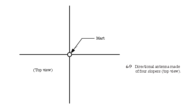
ground, and being fed in the center by coaxial cable. Some of the same comments asobtained for the inverted-vee antenna also apply to the sloping dipole, so please see that section also.Some operators like to arrange four sloping dipoles from the same mast suchthat they point in different directions around the compass (Fig. 6-9). A single four-position coaxial cable switch will allow switching a directional beam around the com-pass to favor various places in the world.
Find the best antennas for TV, radio, and wireless. Compare top antenna deals, use free antenna calculators, follow DIY guides, and buy high-performance antennas with confidence.
Sloping dipole (“sloper” or “slipole”)
The sloping dipole(Fig. 6-8) is popular with those operators who need a low angle of radiation, and are not overburdened with a large amount of land to install the antenna. This antenna is also called the sloper and the slipole in various texts. The author prefers the term “slipole,” in order to distinguish this antenna from a sloping vertical of the same name. Whatever it is called, however, it is a half-wavelength di-pole that is built with one end at the top of a support, and the other end close to the
ground, and being fed in the center by coaxial cable. Some of the same comments asobtained for the inverted-vee antenna also apply to the sloping dipole, so please see that section also.Some operators like to arrange four sloping dipoles from the same mast suchthat they point in different directions around the compass (Fig. 6-9). A single four-position coaxial cable switch will allow switching a directional beam around the com-pass to favor various places in the world.
ground, and being fed in the center by coaxial cable. Some of the same comments asobtained for the inverted-vee antenna also apply to the sloping dipole, so please see that section also.Some operators like to arrange four sloping dipoles from the same mast suchthat they point in different directions around the compass (Fig. 6-9). A single four-position coaxial cable switch will allow switching a directional beam around the com-pass to favor various places in the world.
Subscribe to:
Post Comments (Atom)


No comments:
Post a Comment