Antenna Handbook: 2020

Build The Microcomputer SAP-1 (Continues 1)

As described in article before about the architecture of Microcomputer SAP-1 , in this article we will continue with other part of Microcomputer Diagram Block and circuit .
For you reference , in figure 10-1 as described  have Instruction Register, Accumulator, B Register, Output Register, and Binary Display, We will describe all about it in this article.


Instruction Register

The Instruction register is part of the control unit. to fetch an instruction from the memory the computer does a memory read operation. 

This places the contents of the addressed memory location on the W bus . At the same time, the instruction register is set up for loading on the next positive clock edge.

The contents of the instruction register are split into two nibbles. The upper nibble is a two-state output that goes directly to the block labeled "Controller sequencer". The lowe nibble is a three-state output that is read onto the W bus when needed.

Controller-Sequencer

The lower left block contains the controller-sequencer. Before each computer run, a Low CLR signal is sent to the program counter and a CLR signal to the instruction register.
 

Kivy Example Program "Hello World"


class TestApp(App):
     
            def build(self):  
                return Button(text='Hello World')  
TestApp().run()

Copy and paste the program listing above into Python Shell 2.7.18 or Python Shell 
3.x then save with the name HelloWorld.py, and run with the Run Module.


Build The SAP-1 Microcomputer

This articles is from Book of Digital computer electronics : an introduction to microcomputers , book written by Albert Paul Malvino.

The SAP (Simple-As-Possible) computer has been designed for the beginner. The Main Purpose of SAP is to introduce all the crucial ideas behind computer operation without burying you in unnecessary detail. But even a simple computer like SAP covers many advanced concepts. to avoid bombarding you with too much all at once, we will examine three different generations of the SAP computer.

SAP-1 is the first stage in the evolution toward modern computers. Although primitive, SAP-1 is a big step for a beginner. So, dig into SAP-1, master SAP-1, its architecture, its programming , and its circuits, Then you will be ready for SAP-2. 

The Architecture 


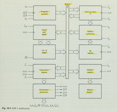
Figure 10-1 shows the (structure) of SAP-1, a bus-organized computer. All register outputs to the W bus are three-state; this allows orderly transfer of data . All other register outputs are two-state; these outputs continuously drive the boxes they are connected to.

The layout of fig. 10-1  emphasizes the registers used in SAP-1. For this reason , no attempt has been made to keep all control circuits in one block called the control unit, all input-output circuits in another block called the I/O unit, etc.

many of registersof Fig. 10-1 are already familiar from earlier examples and discussions. What follows is a brief description of each box; detailed explanations come later.

The Circuit Diagram


Program Counter

The program is stored at the beginning of the memory with the first instruction at binary address 0000, the second instruction at address 0001, the third at address 0010, and so on. The program counter, which is part of the control unit, counts from 0000 to 1111. It is job is to send to the memory the address of the next instruction to be fetched and executed. It does this as follows.

The Program Counter is reset to 0000 before each computer run. When the computer run begins, the program counter sends address 0000 to the memory. The program counter is then incremented to get 0001. After the first instruction is fetched and executed, the program counter sends address 0001 to the memory. Again the program counter is incremented. After the second instruction is fetched and executed, the program counter sends address 0010 to the memory. In this way, the program counter is keeping track of the next instruction to be fetched and executed.

The program counter is like someone pointing a finger at a list of instructions, saying do this first, do this second, do this third, etc. This is why the program counter is sometimes callled a pointer; it points to an address in memory where something important is being stored. 


Input and MAR

Below the program counter is the input and MAR block. It includes the address and data switch registers. These Switch registers, which part of the input unit, allow you to send 4 address bits and 8 data bits to the RAM. As you recall, instruction and data words are written into the RAM before a computer run.

The Memory address register (MAR) is part of the SAP-1 memory. During a computer run, the address in the program counter is latched into the MAR. A bit later, the MAR applies this 4-bit address to the RAM, where a read operation is performed.

The RAM

The RAM is a 16 X 8 static TTL RAM. You can program the RAM by means of the address and data switch registers. This allows you to store a program and data in the memory before a computer run.
During a computer run, the RAM receives 4-bit addresses from MAR (Memory Address Register) and a read operation is performed, In this way , the instruction or data word stored in the RAM is placed on the W bus for use in some other part of the computer. 

On the next article, I will describe  Instruction register, controller sequencer, Accumulator/A Register, Adder/Subtractor, B Register, Output Register, and Binary Display.

What is Filter Circuit ?

filter is a circuit that is capable of passing a specific range of frequencies while block-ing other frequencies. The four major types of filters include low-pass filters, high-pass filters, bandpass filters,and notch filters(or band-reject filters). A low-pass filter passes low-frequency components of an input signal, while a high-pass filter passes high-frequency components. A bandpass filter passes a narrow range of frequencies centered around the filter’s resonant frequency, while a notch filter passes all frequencies except those within a narrow band centered around the filter’s resonant frequency

 Filters have many practical applications in electronics. For example, within a dc power supply, filters can be used to eliminate unwanted high-frequency noise present within the ac line voltage, and they act to flatten out pulsing dc voltages generated by the supply’s rectifier section. 

In radio communications, filters make it possible for a radio receiver to provide the listener with only the desired signal while rejecting all others. 

 Likewise, filters allow a radio transmitter to generate only one signal while attenuating other signals that might interfere with different radio transmitters’ signals. 

In audio electronics, filter networks called crossover networks are usedt o divert low audio signals to woofers, middle-range frequencies to mid range speakers, and high frequencies to tweeters. 

The list of filter applications is extensive.There are two filter types covered in this chapter, namely, passive filter sand active filters. 

Passive filters are designed using passive elements (e.g., resistors, capacitors,and inductors) and are most responsive to frequencies between around 100 Hz and 300 MHz. 

The lower frequency limit results from the fact that at low frequencies the capacitance and inductance values become exceedingly large, meaning prohibitively large components are needed. 

The upper frequency limit results from the fact that at high frequencies parasitic capacitances and inductances wreak havoc.) 

When designing passive filters with very steep attenuation falloff responses, the number of inductor and capacitor sections increases. 

As more sections are added to get the desired response, the greater is the chance for signal loss to occur. Also, source and load impedances must be taken into consideration when designing passive filters. 

Active filters, unlike passive filters, are constructed from op amps, resistors, and capacitors—no inductors are needed. Active filters are capable of handling very low frequency signals (approaching 0 Hz), and they can provide voltage gain if needed(unlike passive filters). 

Active filters can be designed to offer comparable performance to LC filters, and they are typically easier to make, less finicky, and can be designed without the need for large-sized components. 

 Also, with active filters, a desired input and output impedance can be provided that is independent of frequency. One major drawback with active filters is a relatively limited high-frequency range. 

Above around 100 kHz or so, active filters can become unreliable (a result ofthe op amp’s bandwidth and slew-rate requirements). 

At radio frequencies, it is best to use a passive filter

(from Book :  Practical Electronics for Inventors by : Paul Scherz)

Write Now Programmer universal ic programmer kit

Our company is representative for Algocraft Device Programmers, Please contact me for device programmers inquiries Writenow programmers and Writebefore programmers. We shipping worldwide !

Main Features

  • Ultra-fast, universal In-System Programmers
  • True parallel, program up to 8 devices at once
  • Industrial-grade reliability
  • Standalone operations or host controlled
  • Easy to install and to use
  • Compact size, fixture friendly

Introduction

Based on the proprietary WriteNow! Technology, the WriteNow! Series of In-System Programmers is a breakthrough in the programming industry. The programmers support a large number of devices (microcontrollers, memories, CPLDs and other programmable devices) from various manufacturers and have a compact size for easy ATE/fixture integration. They work in standalone or connected to a host PC (RS-232, LAN and USB connections are built-in), and are provided with easy-to-use software utilities.

Features

  • Supports microcontrollers, serial and parallel memories, CPLDs and other programmable devices
  • High-speed, parallel programming
  • Compact size (fixture friendly)
  • Standalone operations or host controlled
  • Designed for easy ATE interfacing
  • Robust and reliable
  • Supports multiple interfaces (JTAG, BDM, SPI, I2C, UART, etc.)
  • Memorizes data on a built-in memory card
  • Programmable power supply output (1.5-13V)
  • Programmable I/O voltage (1.6-5.5V)
  • High-speed I/O
  • USB, LAN, RS-232 (isolated) and low-level interface (isolated)
  • ISP I/O relay barrier (only available on the single-site model)
  • I/O protection
  • Wide range power supply (12-24V)

Powerful and Easy-to-Use Software Utilities

The WriteNow! Series of In-System Programmers can be controlled by a host PC through simple, ASCII strings through a standard terminal interface. On top of that, a powerful user interface is provided which allows to setup and control the instruments through easy, graphical procedures. The WriteNow! Project Generator guides you through the creation and debugging of a programming Project in a few guided steps: device selection, source file creation, board parameter settings, programming flow options, upload and run of the Project.


Models

The WriteNow! Series of In-System Programmers is available in four models, which share a common in-system programming core. Single-site model features a relay barrier on ISP I/O lines.
WN-PRG01A Single-Site In-System Programmer
WN-PRG02A 2-Site In-System Programmer
WN-PRG04A 4-Site In-System Programmer
WN-PRG08A 8-Site In-System Programmer

External Relay Barriers

External relay barriers are available as accessories for multiple-site WriteNow! models.
WN-REB04A Relay Barrier Module for WN-PRG02A and WN-PRG04A
WN-REB08A Relay Barrier Module for WN-PRG08A

Demultiplexer Modules

WN-DM2X2A Demultiplexer Module for WN-PRG02A (4 Channels + Relay Barrier)
WN-DM2X3A Demultiplexer Module for WN-PRG02A (6 Channels + Relay Barrier)
WN-DM2X4A Demultiplexer Module for WN-PRG02A (8 Channels + Relay Barrier)
WN-DM4X2A Demultiplexer Module for WN-PRG04A (8 Channels + Relay Barrier)
WN-DM4X3A Demultiplexer Module for WN-PRG04A (12 Channels + Relay Barrier)
WN-DM4X4A Demultiplexer Module for WN-PRG04A (16 Channels + Relay Barrier)
WN-DM8X2A Demultiplexer Module for WN-PRG08A (16 Channels + Relay Barrier)
WN-DM8X3A Demultiplexer Module for WN-PRG08A (24 Channels + Relay Barrier)
WN-DM8X4A Demultiplexer Module for WN-PRG08A (32 Channels + Relay Barrier)

Silicon Support

  • Adesto
  • Atmel
  • Cypress
  • Giga Device
  • Infineon
  • Microchip
  • Micron
  • Nordic Semiconductor
  • NXP (Freescale)
  • Renesas
  • Sigma Designs
  • Silicon Labs
  • Spansion
  • SST
  • ST Microelectronics
  • Texas Instruments
  • Winbond
New manufacturers and devices are constantly added. Contact us for more information.

Additional Information

You can request additional information through our Information Request Form.

The Best Cheapest Satellite Broadband Plans

IsatHub Satellite Service Plans

The IsatHub service is accessed from your smartphones, iPad , or iPod Touch (tm) or android  device through the control app. The Voice app enables you to send and receive calls via  IsatHub's with dedicated high quality voice line as well as your text messages, and internet even your device is connected to WiFi only. Works with Android Devices and Apple Devices.


Inmarsat IsatHub Service Plans


Inmarsat IsatHub Rental Bundles
Our sales team is waiting to help you determine if the IsatHub will meet your needs and setup your order in minutes. Please call 1-941-208-0664 

Easy To Use

The IsatHub service is accessed from your iPhone, iPad and/or iPod touch or Android[TM] device through the control app. This provides set-up assistance and gives you full control over access to the service as well as visibility of data usage from each device sharing the IsatHub connection. The voice app enables you to use your smart device to send and receive voice calls via IsatHub’s dedicated high-quality voice line, as well as text messages, even if your device is for WiFi use only.

Grab Your World with You 

Imagine a world where you use your phone or tablet seamlessly to talk, text, access the internet and your apps, independently of cellular and fixed networks. Well that world is here with IsatHub, our global smart device connectivity service. So now you can remain productive by having a constant line back to the office and stay in touch with your friends and family wherever you go.

Best Preampfilier for Indoor Outdoor Antenna

Why do I need Pre Amplifier ?

This is common question shows up to you. 

When you TV reception interfere with near FM station or your TV can not pick up several channels. 

These common problems solved with the preamplifier installed.  

Preamplifier helps pick up channels that your non-amplified antenna alone may not be able to pick up. 

Additionally, the preamplifier minimizes pixelization and drop-outs.

What We should look at Preamplifier , before we buy it ? 

These common ideal question and answer must applied to the preAmplifier that you choose. 

Ask these

1.  Does The preamplifier work with any antenna ?  The preamplifier that works with any passive/non-amplified antenna is better than the specific one

2. Does The preamplifier work with VHF & UHF signalsTypical gain for VHF is 20 dB (lo) and 15 dB (hi) and for UHF is 18 dB.

3. Does the preamplifier have an FM trap ? The preamplifier should have built-in FM trap that attenuates FM signal so that it does not interfere with digital TV channels. 

4. What is the noise figure of the preamplifier ? The preamplifier has a typical noise figure of 1 dB for UHF and 3 dB for VHF. 

5. Can I use a splitter with the preamplifier ? The preamplifier can be used to distribute signal to multiple TVs. 

Based on the spec I have mention above, I pick it for you 3 the best preamplifier for indoor outdoor antenna that serve in the market. 


Best Preamplifier Antenna


1. Winegard LNA-200 Bost XT

  • Installs on any outdoor non-amplified TV antenna
  • Bandpass filters remove interfering RF signals
  • Maximum Gain (typical): 18 dB
  • Noise Figure (typical): 1dB
  • Power: +5V at 130mA

2. Channel Master Pre-Amplifier with LTE Filter


  • Can Be Installed Indoor, Outdoor or in Attic Due to its Compact Size and Heavy-Duty Weatherproof Housing
  • Blocks Interference From 3G, 4G, 5G Smartphones and Transmitters with EMI & FM Out of Band Filtering (Does Not Pass FM Radio Signals to Avoid Over Amplification Issues)
  • Improves Signal Quality, Decreases Pixilation and May Increase Number of Channels
  • Button Adjustable Amplification (17 dB/30 dB) with Flexible USB Powering Options

3. RCA Preamplifier for Outdoor Antenna
  • Switchable FM trap reduces interference from FM frequencies
  • Preamplifier for outdoor antennas extends range in low signal strength areas
  • RCA's advanced SmartBoost technology amplifies weak signals to deliver the most channels possible
Another preamplifier for your alternative with almost the same specs are Winegard LNA200S, Channel Master Titan 

How to pointing your dish network azimuth skew and elevation finder ?

Pointing Dish Network

Winegard(tm) Carryout(tm) Anser Antenna is a portable satellite system that required a user elevation setting to automatically acquire the desired satellite. 


Winegard Anser Antenna

As the user, you will need to know which satellite you would like to view and the corresponding elevation angle for that satellite. 

Under “Compatible Satellites,” different popular satellite options are outlined along with the programming offered via each satellite. 

Elevation and coverage maps are also included to help you determine the correct elevation angle and coverage for certain satellites.


The Anser Carryout Antenna for use with Dish Network and Bell TV, and DirectTV.


Parts Of Antenna


Antenna in Deployed Position


Antenna in Stowed Position


Simple step Installation Anser antenna 


  • Find elevation angle - via receiver menu or provided maps*. 

  • Hook up the antenna - manually set the elevation to the correct elevation angle for your area. 

  • Get to the signal meter-screen on your receiver. 

  • Plug in the unitthe unit will search and find the strongest signal. 

  • If the system stops-on a signal but is not on the desired satellite for viewing, the unit will move to the next signal found in 45 seconds. 
  • Once you have signal on your desired satellite - unplug the power to the unit. 

  •   Watch TV! 

How To Pointing Antenna ?

The Principle of Pointing an Antenna, you need only two information, The information about the Azimuth and the elevation number that point the antenna to the Satellite that will serve your receiver ? 

picture courtesy : promaxelectronics.com

See the picture describe the Azimuth the position of antenna from the North compass and the Elevation is the corner degree antenna from horizon . 

Just the simple like that...


*Elevation angles may not be displayed in the receiver menu for satellite 72° (recommended as a single satellite solution for DISH® HD programming) or 129°. 

If the elevation angle is not displayed in the receiver menu, use the provided elevation and coverage maps to find the elevation angle for your current location.

Compatible Satellites

For Dish Network

Set To :

72°: Eastern satellite, recommended for HD programming

129°: Western satellite, majority of HD programming

119°: Majority of std. programming

110°: Some standard programming, limited HD programming


Elevation Maps


How to use the maps ?

  • Determine which satellite you want to point at - Maps are provided for Dish 72, Dish 110, Dish 119, Dish 129, DirectTV 101, Bell TV 82, and Bell TV 91.
  • On the corresponding map-find your location.
  • Determine the elevation angle- closest to your current location.
  • Use this elevation angle to help point your antenna- Keep in mind that the elevation angles provided are approximate. 
  • If having trouble-locking onto signal with the elevation angle provided, try adjusting the angle ±2–3 degrees.


Example :


Your current location is in Colorado, and satellite is Dish 72 for HD Programming. Find your Elevation ?

Answer :

So look at Dish 72 Map below , for Colorado elevation is 33, so adjust your elevation to 33 degree from Horizon.

I attached a US map to make it easier to find your location and match the elevation map


Here the lists elevation maps 

Maps For Dish Network


Maps for DirectTV


Maps for Bell TV


TIP 

The 72° satellite is recommended as a single satellite solution for DISH® HD programming. In the Northwest, the extremely low elevation angle may present issues in getting clear line-of-sight to the satellite. 

In those circumstances, use one of the western satellites (110°, 119°, or 129°). 


Note that the 72° and 129° satellites require an HD receiver. circumstances, use one of the western satellites (110°, 119°, or 129°). 


Note that the 72° and 129° satellites require an HD receiver. 

Here is Video Dish Azimuth and Elevation Pointing for your reference.
Reference : Winegard manual Dish Network