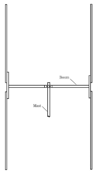
The background for the creation of the Cubic Quad Beam Antenna is due to the existence of shortwave radio stations located in the highlands. previously used a Yagi
antenna which is more suitable for lowland, to transmit worldwide with high voltage input, This antenna is fed in the middle of the current loop, so the end is the
high voltage loop. In the thin air of Quito, Ecuador,the high voltage at the tip causes a corona arc, and that arc periodically destroys the tip of the Yagi element.
so Design station engineer Clarence Moore designed Cubical Quad Beam antenna to solve this problem.
.PNG) |
| Fig 2. Quad Loop Antenna |
The antenna shown in Fig. 1 is actually a quad loop rather than a cubical quad. Two or more quad loops, only one of which needs to be fed by the coax, are used to make a cubical quad antenna. If only this one element is used, then the antenna will have a figure-8 azimuthal radiation pattern (similar to a dipole). The quad loop antenna is preferred by many people over a dipole for two reasons. First, the quad loop has a smaller "footprint" because it is only a quarter-wavelength on each side Fig 1. Second, the loop form makes it somewhat less susceptible to local electromagnetic interference (EMI).
The quad loop antenna (and the elements of a cubical quad beam) is mounted to spreaders connected to a square gusset plate. At one time, carpets were wrapped around
bamboo stalks, and those could be used for quad antennas. Those days are gone, however, and today it is necessary to buy fiberglass quad spreaders. A number of kits are advertised in the web.
The details for the gusset plate are shown in Fig.2 . The gusset plate is made of a strong insulating material such as fiberglass or in marine-grade plywood.
It is mounted to a support mast using two or three large U bolts (stainless steel to pre- vent corrosion). The spreaders are mounted to the gusset plate using somewhat smaller U bolts (again, use stainless steel U bolts to prevent corrosion damage)
The elements can be fed in the center of a horizontal side fig A, in the center of a vertical side fig B , or at the corner fig C
There is a running controversy regarding how the antenna compares with other beam antennas, particularly the Yagi. Some experts claim that the cubical quad has a gain
of about 1.5 to 2 dB higher than a Yagi (with a comparable boom length be- tween the two elements) . In addition, some experts claim that the quad has a lower angle of radiation. Most experts agree that the quad seems to work better at low heights above the earth's surface, but the differencdisappears at heights greater than a half-wavelength.
The quad can be used as either a single-element antenna or in the form of a beam. Figure Fig 3. shows a pair of elements spaced 0.13 to 0.22 wavelengths apart. One element is the driven element, and it is connected to the coaxial-cable feedline directly. The other element is a reflector, so it is a bit longer than the driven element. A tuning stub is used to adjust the reflector loop to resonance.
Because the wire is arranged into a square loop, one wavelength long, the actual length varies from the naturally resonant length by about 3 percent. The driven element is about 3 percent longer than the natural resonant point. The overall lengths of the wire elements are :
1. Driven element : L = 1005/F [MHZ] ft
2. Reflector : L = 1030/F [MHZ] ft
3. Director : L = 975/F [MHZ] ft
with Shortwave Frequency range : 3 - 30 MHz, Center Frequency F[MHZ] = 16.5 MHZ.
One method for the construction of the quad beam antenna is shown in Fig. 4. This particular scheme uses a 12 x 12-in wooden plate at the center, bamboo (or fiberglass) spreaders, and a wooden (or metal) boom. The construc- tion must be heavy-duty in order to survive wind loads. For this reason, it is probbly a better solution to buy a quad kit consisting of the spreaders and the center structural element.


No comments:
Post a Comment