Yagi Antennas

The Yagi beam antenna is a highly directional gain antenna, and is used both in HF and VHF/UHF systems. The antenna is relatively easy to build at VHF/UHF. In fact, it is easier than for HF systems. 

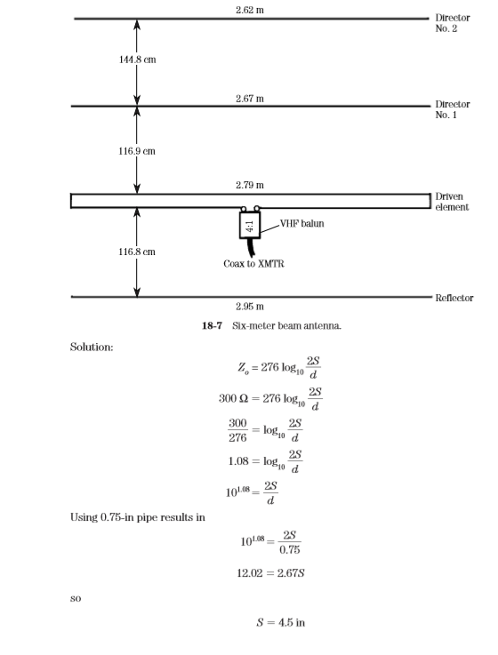
The basic Yagi was covered in Chap. 12, so we will only show examples of practical VHF devices. A 6-m Yagi antenna is shown in Fig. 18-7. This particular antenna is a four-element model. The reflector and directors can be mounted directly to a metallic boom, because they are merely parasitic.

The driven element, however, must be insulated from the metal boom. The driven element shown in Fig. 18-7 is a folded dipole. While this is common practice at VHF, because it tends to broadband the antenna, it is not strictly necessary. 

The dimensions of the driven element are found from Eq. 18.4. Set the equation equal to 300 Ω, select the diameter of the tubing from commercially available sources, and then calculate the spacing.

Example 18-2 Calculate the spacing of a 300-Ω folded dipole when 3⁄4-in tubing is used in its construction.

This Article is from Practical Antenna Handbook by Joseph J. Carr

Collinear Gain Antenna For VHF/UHF Receiver/Transmitter

Gain in antennas is provided by directivity. In other words, by taking the power radiated by the antenna, and projecting it into a limited direction, we obtain the appearance of higher radiated power. In fact, the effective radiated power (ERP) of the antenna is merely its feedpoint power multiplied by its gain. 

Although most antenna patterns are shown in the horizontal dimension (as viewed from above), it is also possible to obtain gain by compressing the vertical aspect. In this manner it is possible to have a vertical antenna that produces gain. Figure 18-6 shows a collinear gain antenna, with vertical polarization and a horizontally omnidirectional pattern. Incidentally, when mounted horizontally the pattern becomes bidirectional.

The collinear antenna shown in Fig. 18-6 is basically a pair of stacked collinear arrays. Each array consists of a quarter-wavelength section A and a half-wavelength section C separated by a quarter-wavelength phase reversing stub B. The phase reversal stub preserves in-phase excitation for the outer element (referenced to the inner element).

The feedpoint is between the two elements of the array (i.e., between the A sections). The coaxial-cable impedance is transformed by a 4:1 balun transformer (see Fig. 18-1A). Alternatively, 300-Ω twin lead can be used for the transmission line. If this alternative is used, then the use of UHF shielded twin lead is highly recommended. If the transmitter lacks the balanced output needed to feed twin lead, then use a balun at the input end of the twin lead (i.e., right at the transmitter).

Coaxial Vertical Antenna For VHF/UHF Receiver/Transmitter

The coaxial vertical is a quarter-wavelength vertically polarized antenna that is popular on VHF/UHF. There are two varieties. In Fig. 18-5A we see the coaxial antenna made with coaxial cable. Although not terribly practical for long-term installation, the coax-coax antenna is very useful for short-term, portable, or emergency applications. 

For example, a boater found himself adrift, and in dire trouble, after a storm damaged the boat. The mast-top VHF antenna was washed away, leaving only the end of the coaxial cable dangling loose. Fortunately, the boat operator was a two-way radio technician, and he knew how to strip back the coaxial cable to make an impromptu coaxial vertical.

The coax-coax antenna shown in Fig. 18-5A uses a quarter-wavelength radiator and a quarter-wavelength sleeve. The sleeve consists of the coax braid stripped back and folded down the length of the coax cable. The maximum length is found from the equation below (actual length is trimmed from this maximum):


The antenna is mounted by suspending it from above by a short piece of string, twine, or fishing line. From a practical point of view, the only problem with this form of antenna is that it tends to deteriorate after a few rainstorms. This effect can be reduced by sealing the end, and the break between the sleeve and the radiator, with either silicone RTV or bathtub caulk. A more permanent method of construction is shown in Fig. 18-5B. The sleeve is a piece of copper or brass tubing (pipe) about 1 in in diameter. An end cap is fitted over the end and sweat-soldered into place. The solder is not intended to add mechanical strength, but rather to prevent weathering from destroying the electrical contact between the two pieces. An SO-239 coaxial connector is mounted on the end cap. The coax is connected to the SO-239 inside the pipe, which means making the connection before mounting the end cap.

The radiator element is a small piece of tubing (or brazing rod) soldered to the center conductor of a PL-259 coaxial connector. An insulator is used to prevent the rod from shorting to the outer shell of the PL-259. (Note: an insulator salvaged from the smaller variety of banana plug can be shaved a small amount with a fine file and made to fit inside the PL-259. It allows enough center clearance for 1⁄8-inch or 3⁄16-inch brass tubing.) Alternatively, the radiator element can be soldered to a banana plug. The normalsize banana plug happens to fit into the female center conductor of the SO-239.

Faraday Feed System Loop Antenna

Another loop antenna is shown in Fig. 16-3. This antenna has a Faraday feed system rather than a capacitor-coupled feed system, as did the Patterson loop. The tuning is accomplished by CA, the series tuning capacitor. The requirement must be met that D1/D2 5.

Magnetic Coupling Loop Antenna

Still another loop is shown in Fig. 16-4. This loop relies on magnetic coupling to perform the coupling of the transmitter. In this loop antenna, the coupling is via a small coupling loop and 50- coaxial cable to the transmitter. Capacitor C1 is used to resonate the loop, whereas capacitors C2 and C3 serve the purposes of loading and resonating the coupling loop. According to Mozzochi (1993), the voltages and currents with respect to the capacitors are


 The radiation patterns for the loop antenna are shown in Fig. 16-5. Note that four elevations are given (0°, 20°, 45°, and 60°). The bottom line is that small transmitting loop antennas are not very good for those who can afford to put up a better antenna, but for those whose tight quarters permit only a small transmitting loop, they are quite viable.