Antenna Handbook

Antenna Grounding Kit

Outdoor Antenna Installation Tips

Looking for more guidance or want to educate yourself before cutting the cord? Here are some tips tailored to safely installing your outdoor TV antenna.

Please note: Every time you move or reconnect your antenna, you must scan for channels on your television. Consult your television owner's manual for more precise guidelines. We include Quick Start guides with all our TV antennas and also provide them here on our website for free.

Installation tips:

  1. Before installing an antenna permanently on a roof or in your attic, test reception in that area and other locations prior to installation. To perform a test, connect the coaxial cable from the antenna to your TV. Then, place your antenna in the desired location. Turn on your TV using your TV and, using your remote, complete a channel scan. Once complete, flip through your TV channels and watch for signal interruptions. Make sure your antenna is installed where you get the best signal and the highest number of available channels.
  2. Higher is always better. Mount the antenna on your roof or in the attic for optimal performance. These locations are more likely to experience fewer obstacles which cause signal interference between the antenna and broadcast towers.
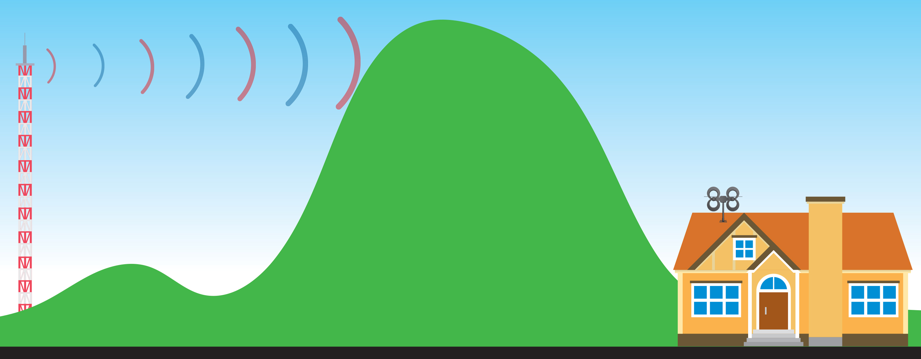
  3. Face the front of the antenna toward the broadcast towers. Even multi-directional antennas require this to achieve the best possible reception. Don't know where your towers are? Visit our transmitter locator or download our free Antenna Point app. 
  4. Check your outdoor antenna regularly for secure coaxial cable connections and signs of corrosion. Sometimes debris or humidity can interfere with reception. Where possible, cover all connections and use waterproof sealant when installing an antenna mast. (See our included sealing pads for reference.)
  5. Installing your antenna near power lines is dangerous. The antenna must be at least 20 ft. (6 meters) away from all power lines. If any part of the antenna or mast assembly comes into contact with a power line, call your local power company. Do not remove it yourself.

Note: Unfortunately, sometimes antennas are returned to us in perfect working order but were returned due to faulty installation techniques. Continue reading for troubleshooting tips.

Troubleshooting tips:

Spotty reception with accessories:

  1. For the best reception, make sure the coaxial cable is the correct length for your installation needs. Similar to getting your antenna up high, terminating your coaxial cable at the right length will provide better reception to your television. 
  2. If you are using a splitter, diplexer, or your cable run must be longer than 100 ft., consider using a preamplifier to boost weak signals. 

Spotty reception:

  1. Reflected signals are also called "multipath interference". For those living close to broadcast towers, signal loss can occur when strong signals bounce off nearby buildings and other surfaces in the area. Aim your antenna in different directions, even sometimes away from the towers, and scan for channels. If this doesn't improve your reception, your installation may require an attenuator.
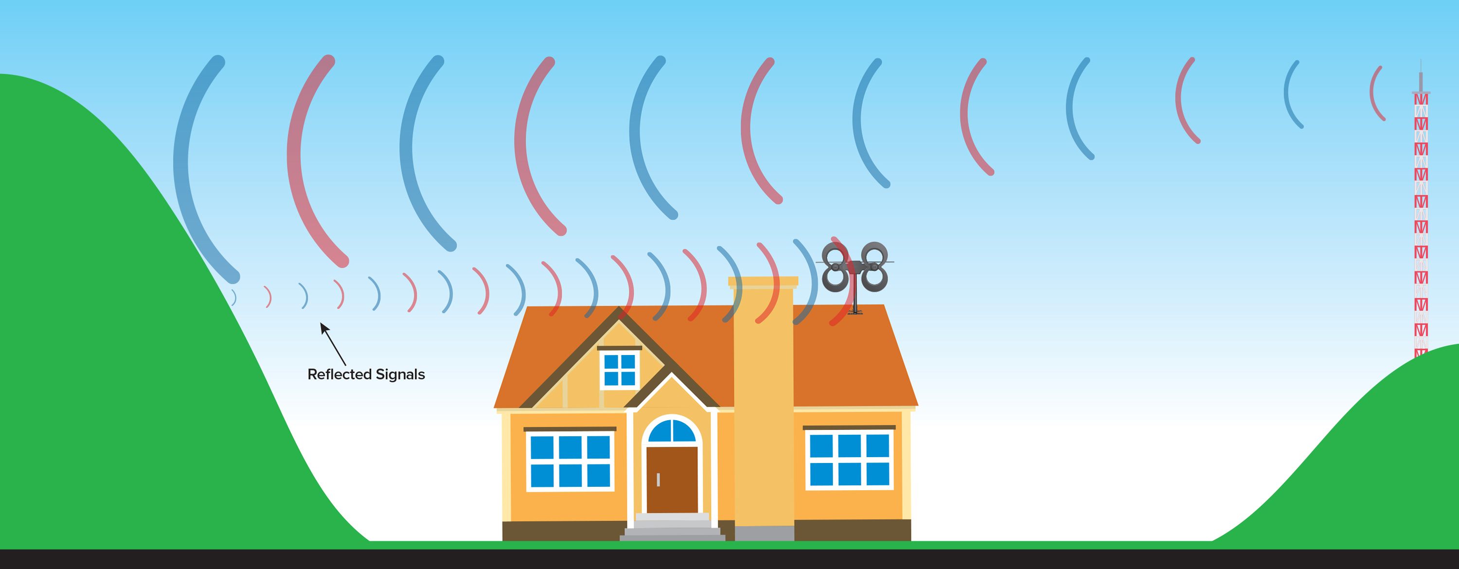
  2. Do not install your antenna near metallic objects or reflective surfaces, as this could also cause signal interference.
  3. Since the switch in 2007 from analog to digital signals, receiving TV signal is "all or nothing". You won't see "fuzz" or "snow" on your TV screen if the signal is weak or there is no signal. When a digital signal is received, it will display crystal-clear on your TV. If the signal is interrupted, your TV screen will be blank.

Combining multiple antennas

When combining multiple antennas on the same mast, keep at least 4 to 6 feet of vertical separation between the two antennas to prevent interference. If you want to combine signals from a UHF antenna with a VHF antenna so there is only one down-lead going into your house, use our UHF/VHF signal combiner with a channel filter for each antenna, designed not to pick up out-of-phase signals through the other antenna. For the best results, use equal lengths of coaxial cable from the output of each antenna when connecting to the UHF/VHF combiner.

Optional grounding information

For outdoor TV antenna installations, grounding the coaxial cable will protect your equipment from voltage surges created by nearby lightning strikes but will not protect from a direct strike. Check your local electrical codes to make sure your installation is in compliance. We recommend calling a professional electrician to advise or install your antenna. We have an educational page with suggestions for grounding your antenna.

Safety precautions:

If you are installing an antenna on the roof, assemble the antenna on the ground. Installing an antenna on windy days can be especially dangerous and even slight winds create strong resistance when attempting to set up an antenna or mast. 

Antennas that are improperly installed or mounted on inadequate structures are very susceptible to wind and weather damage. This damage could become life-threatening. The owner and installer assume full responsibility for the installation and verification that it is structurally sound to support all loads (weight, wind, ice, etc.) and is properly sealed against the elements and leaks.

Antennas Direct®, Inc. is not responsible or liable for any damage or injury resulting from antenna installations or by an antenna system failure due to any unknown variable applications.

Best Antenna Installation Tips

Antenna Installation Tips - For  information on where to place your antenna, mounting, wiring, professional installation, and grounding use this information for your guidance.
How to Install an Outdoor TV Antenna in 7 Steps -  Steps of installation of an Outdoor TV antennas :
1. Prepare and check your instrument and materials

2. Choose the side of a house where it is better to install

3. Install an antenna, connect it to a set-top-box

4. Check the signal and adjust the antenna

5. If the signal is bad, change the orientation or the place of the antenna 

6.  If the signal is good, you have finished.

7. Watch your TV


What You Need

Installation is very simple process, you don't need to have many instruments with you

Pliers

Pliers


You need the pliers to screw nuts, bend a metal wire and cut cables and tiers.


Plastic tiers


You need them to fix cables and rods. It is a good idea to have tiers of different colors and length. 

A metal wire


You need it to fix cables and rods in places where you can’t use tiers.


An electrical tape


You need it to isolate connectors of antenna.


An antenna


Use only antennas recommended by specialists.


RG6 cable with connectors 10-20 meters long is  usually enough for one installation.


Use thick rods or metal rods/pole 1.5-2m for a balcony and a roof installation (don’t use thin rod!)

If you need long pole rods, you may ask the client to prepare them for you.


Don’t use antennas like this is your location far away from TV Tower Station


These two antennas are good only if you are very close to a transmitter tower (no more than 1 km) and conditions are good. 

This is an antenna for cars. You can’t receive good TV signal with this antenna unless there is a special transmitter in your city

This antenna is for vertical polarized signals. You can’t receive a good signal with an antenna like this.


All these antennas are good looking, but they will be working badly. These antennas are for indoor use only. You can use these antennas only if the signal is very good and the conditions are good too. 


Don't use antennas like tihis, This antenna can cost much money. This antenna will not work for a long time. This antenna is not good because birds can make nests inside it.


Recommended Antennas 


I tested many types of antennas and found that these designs showed the best results. You can try different antennas yourself and find the best for you!


Big Antenna


This antenna is big. Use big antennas only if the distance to the transmitter is big (more than 20km).
This antenna will work badly if the distance to the transmitter is small.


Small and medium antennas


The first antennas are medium. You can use these antennas if the distance to the transmitter is medium (5-20km)
Don’t use these antennas without a booster if the distance to the transmitter is very long.

The second antennas can work badly if the distance to the transmitter is less than 5km


This antenna is small. Use a small antenna if the distance to the transmitter is less than 3-5km

Example Phillips Outdoor TV Antenna Installation


Safety Instructions

This part is from Phillips user manual for Safety during Outdoor Antenna Installation, annd can be applied in the same way for other outdoor antenna installation.

Antenna grounding and safety warning

1. Outdoor antennas and lead-in conductors from antenna to a building, should not cross over open conductors of electric light or power circuits. They should be kept away from all circuits to avoid the possibility of accidental contact.

2. Each conductor of a lead-in from an outdoor antenna should be connected with an antenna discharge unit. Antenna discharge units (or Lightning Arrester) should be located outside the building or inside the building between the point of entrance of the lead-in and the TV, and as near as practical to the entrance of the conductors to the building.


Important Safety Notes


If you do not feel comfortable or competent to install this antenna we recommend that you seek the assistance of a qualified professional antenna installer.

Read the instructions for this device thoroughly before attempting installation.
The installation or dismantling of any antenna near power lines is dangerous. 
Each year hundreds of people are killed or injured while attempting to install or service antennas. For your safety and proper antenna installation, read and follow all safety precautions.

Choose an installation site for safety as well as perfomance.
All electric power lines, cable lines and telephone lines look alike. To be safe, assume ANY overhead line can kill you. Do not place an antenna where it could potentially fall on to, or blow into a power line. If in doubt call your electric provider. Let them review your site.
Outdoor antennas should be grounded with an approved lighting arresting device. Local codes may apply. Use 8 AWG or larger ground wire.
Height or other restrictions on antennas may apply to your installation depending on your proximity to an airport, or local ordinances.


Take the time to plan your installation procedure. Do all assembly work on the antenna on the ground. Raise the completed antenna after assembly.


Do NOT work on a wet, snowy or windy day or if a thun- derstorm is approaching. Do NOT use a metal ladder.


If the antenna assembly starts to fall, get away from it and let it fall. Remember that the antenna mast and cable are all excellent conductors of electrical current.


Do NOT install the antenna by yourself. Be sure that there are two other people available for help.


If any part of the antenna should come in contact with a power line . . . 
DON'T TOUCH IT OR TRY TO REMOVE IT YOURSELF. Call your local power company immediately. They will remove it.


Should an electrical accident occur . . . DON'T TOUCH THE PERSON IN CONTACT WITH THE POWER LINE, or you too can become electrocuted. Instead, use a DRY board, stick, or rope to push or pull the victim away from the power lines and antenna. Once clear, check the victim. If he has stopped breathing, immediately administer cardiopul - monary resuscitation (CPR) and stay with him. Have some - one else call for medical help.


Install wire antennas high enough that they will not be "walked into" by people.


Do not install antema wire (s) over or under utility lines.


An antenna is like an eye. A signal is like light. A TV tower is like a lamp. But this light is invisible for human eyes. Any antenna must see a signal. If an antenna sees no signal, a set-top-box or a TV-set can’t work.

Direct signal


A TV signal can be DIRECT or REFLECTED. A TV signal is DIRECT when an antenna sees a TV tower and there are no big buildings between the antenna and the TV tower.

This antenna sees a DIRECT signal


Reflected signal


A TV signal can be reflected from walls, building and trees like light is reflected by a mirror. This signal is called a REFLECTED signal. Not every building, wall or tree can give a good reflected signal.


This antenna sees a REFLECTED signal from the wall


How to point an antenna


An antenna is like an eye. This eye needs to see light. You need to point an antenna to a TV tower or to a reflected signal. 

An antenna has the front end and the rear end. The front end MUST be pointed to a TV tower or to a reflected signal. In this case the antenna will see signal like an eye sees light.

This is the front end of the antenna. You point it to a TV tower or to a reflected signal.


This is the rear end of the antenna. You use it to mount an antenna on a thick bamboo rod, a metal pole etc.

Don’t make your STB blind!

Getting more signal is not always good. If an antenna is big and a TV tower is close, a STB can’t  work properly because it gets blind. It gets blind like a human eye gets blind from strong light. If the signal is strong, use medium or small antennas.

What is the best place for an antenna? (Part 1)


The best place on a house for an antenna:

1. Place an antenna as high as possible. Install an antenna on a roof with a thick bamboo pole if possible.
 
2. Place an antenna on the side from which you can see a TV tower. 

3. Place an antenna on the side from which you probably have a REFLECTED signal.

Not always you can easily understand which side is the best. Sometimes you have to try several different places to get a good signal!


Not always you can easily understand which side is the best. Sometimes you have to try several different places to get a good signal!


What is the best place for an antenna? (Part 2)

At first you need to choose the right side of a building, where to place an antenna. The best side is the side in the direction of a TV tower. You can place an antenna on the best side and point the antenna to a TV tower.


If the client lives not in the best side of a house, you can place an antenna on any side and point the antenna to the nearest tall building, wall, tree or tower. The nearest tall building, wall, tree or tower can give a REFLECTED signal.


Where does a reflected signal come from?


If you don’t see a TV tower and can’t get a good signal from the direction of a TV tower, try to get a REFLECTED signal!


A row of buildings in a street. Try to point an antenna to front of the buildings.


A big building (like the Vattanac building). A big building gives a good reflected signal. Try to point an antenna to high buildings


A big wall or a roof. Try to point an antenna to big walls or to a roof of houses near the antenna.

A big tree. A big tree gives not a good reflected signal, but you can try.


Example of how to point an antenna to a TV tower


This antenna is pointed in the best possible way – directly to the TV tower.


The TV tower is in this direction, but you can’t see it.


If you can’t see the TV tower, but you know where it is – point an antenna in that direction first.


It is very important to find the direction of a TV tower. Use your knowledge of the land to find the direction of a TV tower! You can use Google Map or Open Street Map.


Example of how to point an antenna to the nearest tall building


This antenna is pointed to the nearest tall building. This building can give a REFLECTED signal.


This method is not 100% good. If you don’t have a good signal, try other possibilities.


Example of how to point an antenna to the skycrapper


If you live near a skycrapper building, try to point an antenna to the skyscraper. The skyscraper is tall and can give a REFLECTED signal.


Example of how to point an antenna to the nearest house


These antennas are pointed to the nearest houses. This method is not 100% good, if you don't have a good signal , try another possibilities.


Reference : TV antenna installation guidelines or how to become a good signal hunter - Alexander Serov

The Best Indoor HDTV Antenna for 2022

The Best Indoor HDTV Antenna -  As we know, cable TV, streaming TV services, and satellite TV , as Hulu, Disney+, HBO, NetFlix, and etc, require us to pay a subscription fee every month, and burden the monthly bill for each house, and many people have left it to switch to Aerial TV and Digital TV services which currently have a variety of programs.

Indoor HDTV Antenna
Indoor HDTV Antenna

As consumer reports after tested  many digital Indoor HDTV Antenna , tested with different distance and location from many customers, I picks several popular brands Indoor HDTV Antenna  for your reference before purchase.
Consumer rated recommendation  the antenna based on easy installation, easy setup and get VHF and UHF band, also pick up almost all channel.

Indoor HDTV Antenna  will reduce Your Monthly TV Bill

You can now experience HDTV in the highest quality picture and sound available. Over-the-air broadcasts are transmitted in crystal clear Full HD 1080;  far less compressed than what cable and satellite offer. Many local broadcasts are digitally aired in 5.1 Surround Sound giving you the ultimate sound  stage for watching live television. 

With a digital antenna you can receive free local news, weather, kids shows, sports, cooking, shopping, and sitcoms  from networks like ABC, NBC, CBS, FOX, PBS, CW, ION, and much more with no cost or contracts. And broadcast TV won't be interrupted from service drop outs  (satellite). Quick fact: local sports are broadcast free over-the-air. You just need an antenna.

For those who still want to see local TV programming and don't want to pay subsciptions cost, Indoor HDTV antennas brands such as Clear Stream, RCA, Winegard,  Mohu, 1ByOne are the best choice for TV at home


The Best Powerfull performance Indoor HDTV Antenna with Ultra Thin Antenna material with flexible easy Installation options.

Price : $82.00 from Amazon 

Specifications :

  • Flexible Antenna Material
  • Amplifier Included
  • Detachable cable
  • Long range upto +50 miles
  • Easy Installation


RCA Ultra-Thin, Multi-Directional Indoor HDTV Antenna

Indoor HDTV Antenna with Patented, 360º multi-directional design eliminates need for constant adjustments. RCA's advanced SmartBoost technology amplifies weak signals to deliver the most channels possible while filtering out false signals.

Price : $35.99 from Amazon

Specification 

  • 60 mile range reception
  • Amplifier Included
  • Flexible Antenna Material
  • Easy Installation


Winegard Flatwave Amped Pro HDTV Indoor Antenna


App-enabled to capture the most free TV channels. This indoor HDTV antenna is powered with a technology duo, an amplified Bluetooth signal meter, and Clear Circuit technology to give you quick access to all the channels in your area. The digital amplifier embedded in the antenna boosts available signals by 100%. 
Sort by signal strength or fine-tune to get the channels you want

Price : $104.62 from Amazon

The FlatWave Amped Pro is the only antenna with an actual signal meter integrated into the antenna to provide the best possible customer experience when installing. The Flatwave Amped Pro uses a built-in tuner to get real-time signal data

Specification
  • Capture signal more than 60 miles away
  • Built-in Clear Circuit Technology boosts reception, cuts dropout, and clears pixelation.
  • Ultra low noise (1 dB) digital amplifier is attached directly to the Antenna
  • Bluetooth Signal Meter and Integrated Channel Finder 

1ByOne Amplified Indoor Digital HDTV Antenna

High Performace with on Budget Price , high gain Antenna almost 28dB


Price : $27.99 from Amazon

Specification

  • VHF/UHF Band Frequency Range
  • HDTV Compatible/ ATSC Compatible
  • Amplifier Included

The Best VK3UM downloads

VK3UM downloads -  was a software develop by Dough McArthur,Doug VK3UM. For VK3UM Downloads please click here    , VK3UM downloads software consist of EME Calculator [EMECalc] , EME Planner, VK3UM Libration Calculator [LibCalc], VK3UM Electro Magnetic Radiation Calculator [EMRCalc], Atmosphere , Atmosphere calculates the absorption attenuation at Microwave frequencies for both terresttail and slant paths for Amateur frequencies from 10-241 GHz. and VK3UM Noise Source Planner, VK3UM 4 Stage Inter Digital Filter Design [IDF], Transmission Impedance Calculator, VK3UM Auto Track, VK3UM Sun Noise and Measurements.


The software provides the ability to  :
 • select the Radiation Limit to suit your Governing Authority’s Standard. 
 • select the transmission frequency (1.8MHz to 49GHz).  
 • vary the transmitter output power and associated feed losses.
 • select the transmission mode duty factor and averaging period characteristics.
 • select ground reflection factor if required
 • vary the antenna size and efficiency of a Parabolic reflector or select single or multiple yagi arrays  
 • select pre programmed rectangular aperture antennae types for HF (High Frequency) calculations or adjust antennae gain as necessary.
 • vary the height of the HF antennae and display the resultant on axis Exclusion Zone. (bore sight direct line distance)
 • select metric or imperial display presentation.  
 • save and recall user specific preference configurations as required.  
 
The RF Radiation Calculator provides the On Axis Exclusion Zone (General Public), for both near and far field radiation levels, is displayed in both text and graphical (RFGraph) formats. 
 
The System Performance Calculator will simultaneously display both S/N of the Moon Echo and the Sun and Cold Sky to Ground Y factor levels for variables generally not provided in other calculators. These include the added ability to vary; • 10.7cm Solar flux. 
• dish mesh characteristics.
• derived spill over and feed through values. 
• Preamplifier and pre first amplifier gain and loss characteristics. 

Through out the World many Government Authorities have indicated that they are proposing to implement, or are in the process of implementing mandatory standards of radiation limits pertaining to the Radio Amateur Service.  Because of the nature of EME (Earth-Moon-Earth) and other Amateur communications, radiated power levels can be quite high and may, under certain situations, pose a radiation hazard. This software calculates the level of RF Radiation and specifically addresses the near field radiation characteristics of a circular aperture radiating antennae. (RFGraph.exe). This characteristic could be most significant in being able to demonstrate that an EME Station is able to meet Governing Authority’s radiation limits. 

VK3UM Opening Screen

VK3UM HF Option


Program Aim 

The prime purpose of the software is to define the Radiation Level of the On Axis Exclusion Zone, commensurate with the stations effective radiated power, mode of operation and antennae gain. The secondary purpose is to provide the most accurate calculations for the EME budget, Sun Y factor (relative to the solar flux), and Sky (Cold) to ground Y factor.  The user has the ability to vary all or any of the interacting factors and determine, with a high degree of accuracy, your system’s performance. 
 
 
Screen Options
 
The first time the program is run the default parameters as listed in Part 6 of this document will be displayed.  

The VHF-SHF Screen provides access to the Parabolic Reflector (default) and the yagi Array. To select the yagi array click on the button to the left of the display. Similarly to reselect the Parabolic Reflector display click on its button.  

The HF Screen may be selected by clicking on the small button (HF) in the bottom right hand corner of the frequency panel. The options available within this screen may be selected by clicking one of the available options (Low Gain Antennae, Yagi Array or Parabolic Reflector). Access to all the Low Gain Antennae options may be gained by clicking on the associated panel (it will high light in white) and further choose other options by use of the up/down arrows . To return to VHF-SHF screen click on the SHF button.  

Transmission Mode Form Factor options should be selected in accordance with the Standard chosen. In the case of the FCC OET Bulletin 65 they select Carrier or 100%.  

Six Minute Period Average options should also be selected in accordance with the Standard chosen. In the case of the FCC OET Bulletin 65 they select Conversational or 100%.  

Ground Reflection. Select his option where required. This will depend upon the situation under question and should be applied as appropriate. In the case of the FCC OET Bulletin 65 they stipulate this option (in most instances) as a worse case scenario.  

RF Radiation Standards. Three are provided as indicated plus a variable facility to allow for any other Radiation Limit. Many Countries have as yet to define their Standard and the variable option is provided for such eventualities.  

Transmitter Power. Levels from 1-9999 are provided to cover most Amateur situations.  

Transmission Loss. Actual power measured at the radiator. Adjust to suit your particular situation. Remember to include all feed, relay, balun, and divider losses as appropriate.  

Metric/Imperial Button. Selecting either will reflect on all displayed calculations. Note that this function is a ‘stored parameter’.  

System Performance Calculator. There are 14 variables that the user may adjust to suit their situation. The ability to ‘reverse engineer’ your results provides the user with a system analysis tool of considerable effectiveness. 

 File Handling Options  

The Data button provides access to data file management options. 


Save data allows the user to store as many files, with whatever file name you choose (extension is set to *.dug) .  Get Data allows the user to recall the file as stored above. 

Cancel aborts the process and returns the user to the main screen. 
 
Note. 1 All the screen variables available to the user are stored. 2. You may also cancel the save or get file options by using the cancel option when in these screens. 


Default Option allows for the retrieval of user defined set up parameters. When the program is first initiated the parameters displayed should be changed to suit the users preferred options. They should be stored as ‘default.dug’. This file will be recalled automatically when clicking on the default button. If the file has not been created then the user will receive an error message warning of the requirement. as well as all the other  variables of frequency, sky temperature, LNA, receiver noise figure, band width and system loss factors. The calculator will provide most accurate data for typical installations and allow the user to define and analyse the operational capabilities of the station. 


In the Next Articles I will write about Default Parameters , Parameters Description, Calculation Methods and Display Presentation.