
This Dual Stacked Yagi Antenna can be used for UHF, GSM, WiFi Band from 300 MHz-3000 MHz. The design was done using Yagi Antenna Calculator ANSOF software, you can download ANSOF trial version for free and also for the paid version, which calculated the length , diameter, and spacing of the materials (elements and boom) used in the construction.
The Identical Yagi Antennas were stacked (1020 mm center to center spacing) vertically leading to an increase in gain of 15.4 dB when compared with 12.7 dB gain obtainable from a single Yagi antenna and larger capture area (effective aperture).
This research are written by J.llonno, M. Awoji, J.E Onuh from Physics Department, University of Jos, Jos, Nigeria and Physics Department, Kwararafa University, Wukari, Tarabe state, Nigeria
This design was able to solve the problems of underground noise, interference, low picture quality, low gain, and large beamwidth associatedwith a single Yagi antenna. This antenna can be used for VHF,UHF,GSM, Wi-Fi Band (300–3000 MHz) applications.
Yagi antenna is an example of a resonant directional antenna consisting of driven elements (active components) and parasitic elements (passive components).
An antenna is an arrangement of electrical conductors designed as transceivers of radio waves (Carr, 2001; Volakis, 2007). Antennas convert Radio Frequency (RF) electrical currents into ElectroMagnetic (EM) waves that generate a radiating electromagnetic field.
The driven elements are connected directly to the transmission line (coaxial cable) and receive power from the source. Whereas, the parasitic elements are not connected to the transmission line and receive energy only through mutual induction. Theparasitic elements (directors and reflectors) modify the radiation pattern of the radio waves emitted by the driven element and direct them in a narrow beam in one direction and are arranged parallel to the driven elements.
The reflector is usually longer than the driven element by 5% and acts as a concave mirror because it reflects the electromagnetic energy incident on it from the driven elements. The director is shorter than the driven element by 5% and acts as a convex mirror as it beams up the incident energy from driven element
(Milligan, 2005).
Antenna gain is the measure of the ability of antenna arrays to concentrate the radiated power in a given direction. High-gain antenna radiates energy in a particular direction whereaslow-gain antenna radiates energy in all directions equally. Gain is described using terms suc has antenna gain, power gain, directivity or directive gain. The antenna gain of the Yagi antenna isgreatly dependent on the dipole gain and the number of elements; and is given by (Ochalaand Okeme, 2011):
G = 1.66 N (1)
where 1.66 is the dipole gain and N is the number of elements
When Yagi antennas are stacked, there is an increase in gain and a decrease in the beam-width. The increased gain is due to the reduction in beam-width.
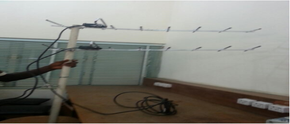
There are two types of stacking namely; vertical stacking and horizontal stacking (Blake, 1996; Balanis, 2005, 2008). Stacking two identical antennas on a common vertical mast as seen in Figure 2 significantly narrows the vertical beam-width angle.
That is, vertically stacked antennas effectively reject those interfering signals arriving from above or below their horizontal plane than that of a single antenna. In this process, gain increases with about 2.5 dB over that of a single antenna (Straw, 2000).
While stacking two identical Yagi antennas side by side in a horizontal plane significantly narrows the horizontal beam-width angle. That is, the antenna combination “sees” fewer interfering signals arriving from the sides while its vision up and down (in a vertical plane) is virtually unaffected. In this process, gain increases approximately 1.2 dB over that of a single antenna (Straw, 2000).
The stacking distance can be calculated using Equation 2 (Milligan, 2005).
S = 57/BW (2)
where S is the stacking distance and BW is the Beam-Width angle
This research work is carried out to solve the problems of underground noise, interference, picture quality, low gain, and large beam-width associated with a single Yagi antenna by stacking two identical Yagi antennas. Vertical stacking was used in the implementation because of the higher gain and greater coverage area.
Materials and Methods
Materials The materials used are:
1. Aluminum Boom
2. Screw nails
3. Elements
4. Coaxial cable (75 Ω)
5. Plastic insulators
6. Tape
7. Drilling machine
8. Hacksaw
9. Mast or pole for mounting of the antenna
Methods Design of Yagi Antenna An online Yagi antenna calculator (AN-SOF Antenna Simutor) was used for the simulation with design frequency of 889 MHz. The Yagi antenna designed has 8 elements: a reflector, a driven element, and 6 directors with dimensions shown in Table 2
Design Implementation The antenna was constructed using aluminum rods for antenna elements, 2cm-squared metal rodas boom, hacksaw for cutting the materials, gimlet for drilling holes, screw nails for fastening theelements to the boom, measuring tape, welding machine, 75-ohm coaxial cable as transmissionline and feeders to house the terminals of the folded dipoles.
The elements were first measured as stated in Table 2. Holes were drilled at the midpoints of the aluminum rods and boom constructed. A reflectorunit and six directors were cut out. Holes were drilled on them and the directors were screwed into their appropriate positions.
Plastic insulators were used to insulate the directors form the supporting boom.The folded dipole (driven element) was constructed by folding aluminium rod on a bending jig to obtain the folded dipole.A junction box was used to support the folded dipole on the boom.
Openings were made on the side of the junction box using a drilling machine to allow fitting of the dipole and the coaxial cable. The feeder was fixed to the director boom with screw nails and the terminal of the folded dipole was then fixed to the inside of the feeder.
With the feeder and folded dipole in place, the reflector and director units were fixed.The relative spacing between elements for optimal reception was determined as follows as shown in Table 3.The antenna was duplicated and were stacked vertically at 1020 mm. Table below shows Length of rodrequired to produce resonant dipole
Approximately one wavelength spacing (at lowest channel frequency) between antennas was maintained.
Finally, the folded dipoles were connected together by means ofa coaxial cable which serves as the transmission line. Table below shows Simulation Result.
Table below shows Normalised Spacing betwen Elements
Table below shows Single and Stacked Yagi Results compared
The results of this finding have shown that dualstacked Yagi antenna offers high gain compared with single Yagi antenna in operation covering channels in VHF, UHF,GSM, and Wi-Fi bands. This design when properly matched to a feeder cable can solve the problems of underground noise, interference, low picture quality, low gain,
and large beam-width posed by single Yagi antenna.
No comments:
Post a Comment