CONDUITS FOR TRANSPORTING RF SIGNALS between elements of a system. For example, transmission lines are used between anexciter output and transmitter input, and between the transmitter input and its out-put, and between the transmitter output and the antenna. Although often erro-neously characterized as a “length of shielded wire,” transmission lines are actuallycomplex networks containing the equivalent of all the three basic electrical compo-nents: resistance, capacitance, and inductance. Because of this fact,
transmissionlines must be analyzed in terms of an RLC network.
Parallel and coaxial lines
This article will consider several types of transmission lines. Both step-functionand sine-wave ac responses will be studied. Because the subject is both conceptualand analytical, both analogy and mathematical approaches to the theory of trans-mission lines will be used.Figure 3-1 shows several basic types of transmission line. Perhaps the oldest andsimplest form is the parallel lineshown in Figs. 3-1A through 3-1D. Figure 3-1A shows an end view of the parallel conductor transmission line. The two conductors,of diameter d, are separated by a dielectric (which might be air) by a spacing S.These designations will be used in calculations later. Figure 3-1B shows a type ofparallel line called twin lead. This is the old-fashioned television antenna transmis-sion line. It consists of a pair of parallel conductors separated by a plastic dielectric.TV-type twin lead has a characteristic impedance of 300 Ω, while certain radio trans-mitting-antenna twin lead has an impedance of 450 Ω. Another form of twin lead isopen line, shown in Fig. 3-1C. In this case, the wire conductors are separated by anair dielectric, with support provided by stiff (usually ceramic) insulators. A tie wire(only one shown) is used to fasten each insulator end to the main conductor. Someusers of open line prefer the form of insulator or supporter shown in Fig. 3-1D.

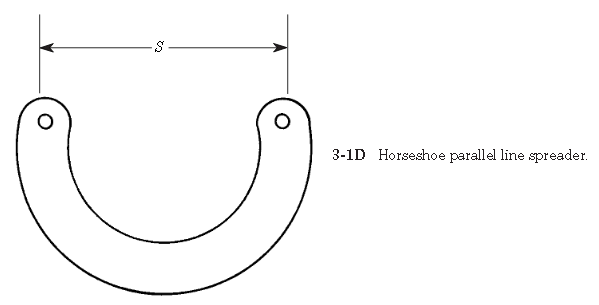
This form of insulator is made of either plastic or ceramic, and is in the form of a U. Thepurpose of this shape is to reduce losses, especially in rainy weather, by increasingthe leakage currents path relative to spacing S.Parallel lines have been used at VLF, MW, and HF frequencies for decades. Evenantennas into the low VHF are often found using parallel lines. The higher imped-ance of these lines (relative to coaxial cable) yields lower loss in high-power appli-cations. For years, the VHF, UHF, and microwave application of parallel lines waslimited to educational laboratories, where they are well suited to performing exper-iments (to about 2 GHz) with simple, low-cost instruments. Today, however, printedcircuit and hybrid semiconductor packaging has given parallel lines a new lease onlife, if not an overwhelming market presence.Figure 3-1E shows a form of parallel line called shielded twin lead. This type of lineuses the same form of construction as TV-type twin lead, but it also has a braided shield-ing surrounding it. This feature makes it less susceptible to noise and other problems.The second form of transmission line, which finds considerable application atmicrowave frequencies, is coaxial cable(Figs. 3-1F through 3-1L). This form ofline consists of two cylindrical conductors sharing the same axis (hence “coaxial”),and separated by a dielectric (Fig. 3-1F). For low frequencies (in flexible cables)the dielectric may be polyethylene or polyethylene foam, but at higher frequenciesTeflonand other materials are used. Also used, in some applications, are dry air anddry nitrogen.

Several forms of coaxial line are available. Flexible coaxial cable is perhaps themost common form. The outer conductor in such cable is made of either braid or foil(Fig. 3-1G). Television broadcast receiver antennas provide an example of such cablefrom common experience. Another form of flexible or semiflexible coaxial line is heli-cal line(Fig. 3-1H) in which the outer conductor is spiral wound.Hardline(Fig.3-1I) is coaxial cable that uses a thin-wall pipe as the outer conductor. Some hardlinecoax used at microwave frequencies has a rigid outer conductor and a solid dielectric.Gas-filled lineis a special case of hardline that is hollow (Fig. 3-1J), the centerconductor is supported by a series of thin ceramic or Teflon insulators. The dielec-tric is either anhydrous (i.e., dry) nitrogen or some other inert gas.Some flexible microwave coaxial cable uses a solid “air-articulated” dielectric(Fig. 3-1K), in which the inner insulator is not continuous around the center con-ductor, but rather is ridged. Reduced dielectric losses increase the usefulness of the
cable at higher frequencies. Double-shielded coaxial cable (Fig. 3-1L) provides anextra measure of protection against radiation from the line, and EMI from outsidesources, from getting into the system.Stripline, also called microstripline(Fig. 3-1M), is a form of transmission lineused at high UHF and microwave frequencies. The stripline consists of a criticallysized conductor over a ground-plane conductor, and separated from it by a dielec-tric. Some striplines are sandwiched between two groundplanes and are separatedfrom each by a dielectric.
(from Practical Antenna Handbook by Joseph J Carr)
The simple broadband TV antenna works at the 615- 765- MHz. Antenna has input impedance 300- Ohm at
the pass band. Antenna may be used with antenna
amplifier that has such input impedance.
The antenna is a variant of the famous Chireix- Mesny
Antenna.
Antenna may be used with coaxial cable with
broadband transformer. switched to the TV 150- MHz.
Figure 1 shows design of the antenna.
Figure 2
shows impedance of the antenna (antenna placed at
7- meter above the real ground). Figure 3 shows SWR
of the antenna (antenna placed at 7- meter above the
real ground). Figure 4 shows DD of the antenna
(antenna placed at 7- meter above the real ground).
The MMANA model of the Chireix- Mesny TV Antenna
may be loaded: http: //
www.antentop.org/018/chireix_018.htm
Note I.G.: Chireix- Mesny Antenna was designed in
France by Henri Chireix, Chief Engineer of the Societe
Francaise Radiotelectrique, and Rene Mesny,
Professor of Hydrography in the French Navy. Papers
on the antenna were published (in different variations)
in the 1926- 1928s. Patent H. Chireix: French Patent #
216,757, filed Mar. 10, 1926.
Antenna originally was used for directive radiation and
reception at short waves. Lately the antenna was
widely used at VHF- UHF waves.
(Source : Antentop)
Below it is
described one of those antennas- it is a Rhombic
Antenna. Rhombic Antenna is easy to make and at the
same time has perfect parameters.
Rhombic Antennas are easy to build and at the same
time has high gain and good diagram directivity.
However the antennas have some lack. Such antennas
required lots space for installations and need at least
for masts instead one that used to support traditional
directional antennas.

Figure 1 shows design of the Rhombic Antenna.
Rhombic Antenna is a rhomb that hang up horizontally
at the ground. Feeder is connected on to one sharp
angle of the rhomb. Terminated resistor is connected
on to far sharp angle of the rhomb. The resistor’s value
should be equal to the impedance of the rhomb at the
working frequencies of the antenna. As usual the value
is near 700- Ohm. Working frequencies of the antenna
may have pass band in hundreds megahertz. So using
such matched resistor allows create a super broadband
antenna that has impedance near 700- Ohm at the
frequencies window in several hundred megahertz.
High gain and high directivity of the rhomb antenna
could be explained by combining gain and diagram
directivity of the parts of the antenna. The antenna
consists of four wires with traveling wave.
Figure 2
shows the combination. Each wire has own gain and
diagram directivity.
The gain and diagram directivity depends on ratio the
length of the wire to the working wavelength. So, the
summary gain and diagram directivity depends on the
ratio the length of the wire to the working wavelength
and to the sharp angle of the rhomb.
Table 1 shows data for Rhombic Antenna with different
parameters. To keep such parameters antenna should
be placed above the ground at height not less the 2- 3
wavelength of the working band of the antenna.
Antenna may be fed by open ladder line with wave
impedance 300… 600- Ohm. At this case the antenna
could be matched at all working frequencies band.
Antenna may be fed through a coaxial cable when two
simple matching transformers are used.

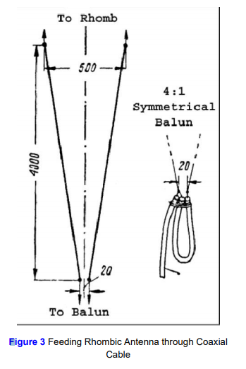
Figure 3
shows feeding Rhombic Antenna through a coaxial
cable. First transformer is a broadband transformer
made on two wire ladder line. It is two wires line with
varying wave impedance on the length.
The wave impedance of the line changes from 700- Ohm at rhomb side to 300- Ohm at coaxial cable
side.At coaxial cable side the coaxial cable should not
connect straight away to the line. Coaxial cable
connected to the line through a symmetrical
transformer 4:1 made on lengths of the used coaxial
cable. The transformer makes symmetrical and
provides matching of the Rhombic Antenna to coaxial
cable. Loop of the coaxial cable should have electrical
length lambda/2. To calculate such transformer you
need to know the shortening coefficient of the used coaxial cable.
It is possible to use coaxial cable with any wave
impedance- 50 or 75 Ohm. Matching impedance of the
4:1 transformer depends on the coaxial cable. At 50- Ohm cable it is got transformer 200:50- Ohm, at 75- Ohm cable it is got transformer 300:75- Ohm.
Transformer 300:75- Ohm should have best matching
result with open line transformer. There are lots link in
the internet how the transformer may be calculated.
One of them is:http://www.nlemma.com/calcs/dipole/balun.htm. When the coaxial
cable symmetrical transformer is used the broadband
of the antenna depends on the broadband of the
transformer. As usual coaxial cable transformer has
good matching at the 5% frequencies band calculated
from the central working frequency of the transformer.
So, when such transformer is used the broad band of
the Rhombic Antenna is limited to pass band of the
transformer.
Antenna may be made from a strand wire in diameter
2… 3- mm. It may be copper, aluminum or bimetal
(with copper or aluminum layer) wire. Terminated
resistor at the antenna may be any small power noninductive resistor. This one should be protected from
atmospheric influences. (Source : Antentop)
The simple broadband TV antenna works at the 580- 760- MHz. Passband of the antenna is 180- MHz.
Antenna has input impedance 300- Ohm at the pass
band.
The Design also can modified from Band frequency 470-806 and with impedance 50 Ohm.
Antenna may be used with antenna amplifier
that has such input impedance. Antenna may be used
with coaxial cable with broadband transformer.
The antenna is critical to any nearby metal subjects. Place the antenna with isolator connected to Antenna body and tower or antenna holder.
They can destroy the DD of the antenna. Space in 50
cm near the antenna should be free from such metal
or conductive subjects. If antenna is used for reception
purposes the best way is place low noise amplifier at
the antenna terminal.
LNA or Low Noise Amplifier can be made with 2SC3358 or 2SC3355, Low Noise Wideband Amplifier 0 - 1 GHz
 Figure 1 shows view of the antenna. Figure 2 shows
design of the antenna. Figure 3 shows impedance of
the antenna (antenna placed at 7- meter above the
real ground). Figure 4 shows SWR of the antenna
(antenna placed at 7- meter above the real ground).
Figure 5 shows DD of the antenna (antenna placed at
7- meter above the real ground).
The MMANA model of the Broadband TV Antenna
may be loaded: http: //
www.antentop.org/018/ur0gt_tv_018.htm (Source : Antentop with modification in content)
Figure 1 shows view of the antenna. Figure 2 shows
design of the antenna. Figure 3 shows impedance of
the antenna (antenna placed at 7- meter above the
real ground). Figure 4 shows SWR of the antenna
(antenna placed at 7- meter above the real ground).
Figure 5 shows DD of the antenna (antenna placed at
7- meter above the real ground).
The MMANA model of the Broadband TV Antenna
may be loaded: http: //
www.antentop.org/018/ur0gt_tv_018.htm (Source : Antentop with modification in content)


