Reducing Capacitance on Coil Inductance

A capacitance is formed whenever two conductors are side by side. A coil produces capacitance as well as inductance because the turns are side by side. Unfortunately, with large multiturn loops, this capacitance can be quite large. The “distributed capacitance” of the loop causes a self-resonance with the inductance. The loop does not work well at frequencies above the self-resonant point, so it is sometimes important to raise the self-resonance to a point where it does not affect operation at the desired frequencies. 

Figure 15-13 shows a solution that raises the self-resonant point. The turns are broken into two or more groups and separated by a space. This method reduces the effective capacitance by placing the capacitances of each group of wires in series with the others.

For Sale Antena Yagi Wifi 2.4 2,4 GHz Antenna 25dbi RP-SMA Modem Support WLAN

WIFI LAN WLAN antenna for Modem PCI Card and Router.
 
 Price US$50 , with shipping cost and tax
 
 Package contents:
- Yagi antenna for wifi, just like in the product photo.

Description:
100% Brand New
High quality
This is a versatile high performance directional WiFi antenna.
Easy installation, good looking.

Specifications:
Color: Silver
Cable length: 150 cm
Bandwidth: 2400MHz
Maximum Power-W: 50
Input impedance: 50 Ohms
Bandwidth-MHz: 100
Product size: 50 cm x 7cm x 3cm
Gain: 25 dBi
Vertical lobe width: 23 "
Horizon lobe width: 26 "

Attention: RP-SMA Male Connector (No pin inside).
This item supports 2.4 GHz frequency only (Wifi / WLAN / WiMax).

Package Included: 1 x 16-unit Fish Bone Fin-Antenna (W-2.4G-16).

Type of Packing: Safety Plastic bag + Free Bubblewarp!
 
Please Order to hadisyarief@gmail.com 

For Sale Antenna Shark Hybrid for Cars

Description Radio shark fin antenna new hybrid car Jazz Brio Mobilio BRV HR, BMW, 
Mercedes, Volvo, all Suitable Sedan and MPV Cars
 
Only US$ 7.99 per pcs, shipping cost and tax not include
 
Ready A LOT OF STOCK.
Please Tell us The Color / Number When Ordering
Available colors:
- 1. RED
- 2. SILVER
- 3. BLACK
- 4. WHITE
- 5. YELLOW
- 6. BLUE
- 7. RED MARON
- 8. ABU
- 9. MODERN STEEL

Shark Fin Hybrid Model Antenna.
Can function as an FM Radio antenna.
Already follows 3M adhesive glue and bolts.
Installation in bolt and paste.

Contact : hadisyarief@gmail.com

Loop Amplifier

Sharpening the loop 

Many years ago, the Q-multiplier was a popular add-on accessory for a communications receiver. These devices were sold as Heathkits, and many construction projects could be found in magazines and amateur radio books. 

The Q-multiplier has the effect of seeming to greatly increase the sensitivity of a receiver, as well as greatly reducing the bandwidth of the front end. Thus it allows better reception of some stations because of increased sensitivity and narrowed bandwidth. 

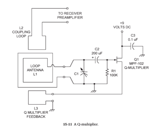
A Q-multiplier is an active electronic circuit placed at the antenna input of a receiver. It is essentially an Armstrong oscillator, as shown in Fig. 15-11, that does not quite oscillate. These circuits have a tuned circuit (L1/C1) at the input of an amplifier stage and a feedback coupling loop (L3). The degree of feedback is controlled by the coupling between L1 and L3. The coupling is varied by varying both how close the two coils are and their relative orientation with respect to each other.

Certain other circuits use a series potentiometer in the L3 side that controls the amount of feedback. The Q-multiplier is adjusted to the point that the circuit is just on the verge of oscillating, but not quite. As the feedback is backed away from the threshold of oscillation, but not too far, the narrowing of bandwidth occurs, as does the increase in sensitivity. It takes some skill to operate a Q-multiplier, but it is easy to use once you get the hang of it and is a terrific accessory for any loop antenna.

Loop amplifier 

Figure 15-12 shows the circuit for a practical loop amplifier that can be used with either shielded or unshielded loop antennas. It is based on junction field effect transistors (JFET) connected in cascade. The standard common-drain configuration is used for each transistor, so the signals are taken from the source terminals. The drain terminals are connected together and powered from the
12-V dc power supply.


A 2.2- F bypass capacitor is used to put the drain terminals of Q1 and Q2 at ground potential for ac signals while keeping the dc voltage from being shorted out. The two output signals are applied to the primary of a center-tapped transformer, the center tap of which is grounded. 

To keep the dc on the source terminals from being shorted through the transformer winding, a pair of blocking capacitors (C4, C5) is used. The input signals are applied to the gate terminals of Q1 and Q2 through dc blocking capacitors C2 and C3. A pair of diodes (D1, D2) is used to keep high-amplitude noise transients from affecting the operation of the amplifier. These diodes are connected back to back in order to snub out both polarities of signal. 

Tuning capacitor C1 is used in lieu of the capacitor in the loop and is used to resonate the loop to a specific frequency. Its value can be found from the equation given earlier. The transistors used for the push-pull amplifier (Q1, Q2) can be nearly any general-purpose JFET device (MPF-102, MPF-104, etc.). A practical approach for many people is to use transistors from service replacement lines, such as the NTE-312 and NTE-316 devices.

Using a loop Antenna

Most readers will use a loop for DXing rather than hidden transmitter hunting, navigation, or other RDF purposes. For the DXer, there are actually two uses for the


loop. One is when you are a renter or live in a community that has routine covenants against outdoor antennas. In this situation, the loop will serve as an active antenna for receiving AM BCB and other low-frequency signals without the neighbors or landlord becoming PFJs (“purple-faced jerks”). The other use is illustrated by the case of a friend of mine. He regularly tunes in clear channel WSM (650 kHz, Nashville) in the wee hours between Saturday evening (“Grand Ole Opry” time) and dawn. However, this “clear” channel of WSM is not really so clear, especially without a narrow filter in the receiver. He uses a loop antenna to null out a nearby 630-kHz signal that made listening a bit dicey and can now tape his 1940s–1950s vintage country music. It is not necessary to place the desired station directly in the main lobes off the ends of the antenna but rather to place the nulls (broadside) in the direction of the offending station that you want to eliminate. So what happens if the offending station and the desired station are in a direct line with each other and your receiving location is in the middle between them? Both nulls and lobes on a loop antenna are bidirectional, so a null on the offending station also will null the desired station in the opposite direction. One method is to use a sense antenna to spoil the pattern of the loop to a cardioid shape. Another method is to use a spoiler loop to null the undesired signal. The spoiler loop is a large box loop placed 1 to 3 ft (found experimentally) behind the reception loop in the direction of the offending signal. This method was first described by Levintow and is detailed in Fig. 15-10. The small loopstick may be the antenna inside the receiver, whereas the large loop is a box loop such as the sports fan’s loop. The large box loop is placed about 33 to 100 cm behind the loopstick and in the direction of the offending station. The angle with respect to the line of centers should be 60° to 90°, which also was found experimentally. It is also possible to use two air core loops to produce an asymmetrical receiving pattern.