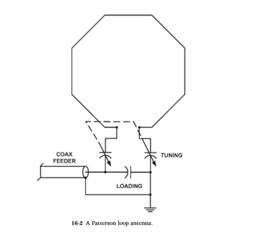
Army Loop Capacitive Coupling Configurations for Small Magnetic Loops-The U.S. Army Loop antenna was designed by Kenneth H Patterson working for Department of the Army, US Army Limited War Laboratory, Aberdeen Proving Ground, Maryland. Patterson first described this configuration in Electronics magazine, August 21 1967. The Patterson (1967) loop antenna is shown in Fig. 16-2. It is made from 1.5-in copper tubing. Segments are cut and are joined together by eight 45° elbow joints, giving the octagon shape. Each segment is 0.5 ft long. The tuning is accomplished by three capacitors, two of which are a split-stator unit (two capacitors on the same shaft). The tuning control is the split-stator capacitor, whereas the loading control is a single capacitor.
The Patterson Army Loop Antenna, A simple portable HF antenna that is easy to deploy, and ideal for NVIS propagation.
You may have heard all sorts of stories about the use of electrically small tuned loop
antennae on HF, many of them erroneous. This essay plans to set the record straight, and
also to describe a very effective portable antenna for 80, 60 and 40 metres which any
ham can build.
There are two main types of loop antennae: they can be categorised by size: large, over
one quarter wavelength circumference (for example a cubical quad); and small, less than
a quarter wavelength circumference. It is the second type that is of interest here.
In order to achieve good matching to the transceiver, and high efficiency, a small loop
needs to be tuned by a capacitor between its ends. High currents flow in the loop, hence it
needs to have very low resistance. Since high voltages exist on the ends (several
thousand Volts when running 100 W), the tuning capacitor needs a good voltage rating,
as well as low resistance.
Types of small loop
There are broadly two types of small loop antenna, the inductively matched type, and the
Army Loop type. Both have advantages. For the higher bands, the inductively matched
type is probably better, as it offers remote operation and is easily rotated.
Efficiency can
also be high because the high voltages are at the top, well above ground. Unfortunately it
is mechanically complex, not easily portable, usually requires a vacuum variable
capacitor, and not suited (because of size) to the lower bands.
The Army Loop,[1] on which I will concentrate, suits the lower bands, and for
convenience is best operated from close to the antenna, although once tuned up, the feed
line can be any length. The tuner is at the bottom, where the high voltages will be. This
type uses capacitive coupling and matching, and is mechanically simple and highly
portable, as I will describe.
One of the major advantages of a loop antenna for portable use (holidays, Field Day,
Emergency operation) is that it has a very small ‘footprint’ on the ground. An 80/40
Army loop occupies only about 16 square metres of real estate.
An 80/40 trapped dipole
requires nearly 400 square metres, a fan dipole even more, when you consider all the
poles and guy ropes.
However (despite what you may have heard), effectiveness (signal strength at the other
station, quality of reception) need not suffer if a few simple guidelines are followed.
Experience has shown that signals from a well-deployed loop can be the same as, or at
most a few dB weaker that from a full-sized, well elevated dipole over a good ground.
Which is another way of saying that the small loop can easily hold its own with other
portable antennae, which are frequently not well elevated, and are used over indifferent
ground. Ground is not an issue with the Army Loop.
Construction and Assembly
The Army Loop which I will describe is roughly diamond shaped, sometimes in practice
almost circular, with a circumference of 10 metres. It is supported by just one mast, about
5 to 6 metres tall, and with four guy wires. Figure 1 shows the layout.

As you can see, I’ve used a mast consisting of three 1.8 metre steel poles (the well known
ZC1 poles), although wooden, bamboo or fibreglass poles, such as tent poles, would be
better. The mast needs to support a reasonable weight.
The actual antenna loop is made of a new 10 metre domestic extension lead, with the
plug and socket discarded, and all three 1 mm stranded wires connected in parallel to
robust crimped fork terminals.
This is the cheapest way to buy cable: it cost me $10, the
guy ropes a further $10.
The mast is supported by four 7.5 metre braided polypropylene ropes, in reality two 15
metre lengths, fastened at the centre over a small PVC conduit stub at the top of the mast.
The antenna loop is carried on one of these 15 metre lengths, tied to it with tape or cable
ties.
You could add a second identical loop to the other guys, and in this way have a
choice of radiation pattern direction (the loop has a roughly cardioid pattern). I don’t
recommend using a smaller loop for higher bands on the other guys, as it then becomes
difficult to bring the ends back to the tuner unless the apex of the guys is lower down the mast. As described, the antenna will nicely tune from about 3 MHz to nearly 8 MHz, so
covers 80, 60 and 40 metres.

Mechanically, the loop is very simple in concept, and very easy to deploy. This type of mast can be erected in five minutes by one person. You mark a spot on the ground for the mast, assemble it, pace out 4.5 metres each way, place four tent pegs, connect the ends of the guys, raise the mast, then adjust the guys to keep the mast straight. Finally, untangle and connect up the loop.
Army Loop History
This type of antenna was developed by Kenneth H. Patterson for the US Army, and it
was first described in Electronics in 1967.[2] The purpose was to provide a small,
efficient, portable and quickly deployed antenna for use in difficult terrain where highangle radiation (NVIS) was required. The idea wasn’t new, but his design took great care
to achieve the highest efficiency. Lewis McCoy’s subsequent QST article [3] describes
the antenna and tuner. McCoy was not able to achieve such good results as the Army, but
we now know a lot more about this antenna than McCoy did in 1968.
The Patterson design used eight heavy loop sections fabricated from gold-plated
Aluminium tubing. We have found that if you use a single continuous heavy wire loop,
(appliance cable, not coax) you can achieve excellent results without the losses
associated with joints, and also achieve a cheaper and more portable result.
The Loop Tuner
The Army Loop Tuner is unusual in that it contains no inductors. It is the loop itself
which is the inductor. The loop is usually tuned by a split-stator capacitor, while match to
50 Ohm is provided by another smaller capacitor. Take a look at Figure 3.
 |
While the upper capacitor C1 (TUNE) is shown as a split-stator type, you could use a
dual-gang variable capacitor of suitable voltage rating, as I did. Whatever you do, you
must avoid having sliding or rotating contacts in the main current path (shown with
heavy lines). For example, you should not use two coupled separate capacitors. There can
be in excess of 10 A flowing in this path, and even the slightest resistance will cause loss.
This capacitor should also be able to withstand 10 kV (for 100 W). In fact, the more
efficient your antenna is, the more this becomes a problem. This capacitor should be at
least 150 pF per section, preferably more if you hope to cover 80 and 40 metres with one
loop. A high quality broadcast variable is quite suited to low power. Use a vernier or
planetary drive for C1, as tuning will be very sharp.
The second capacitor C2 (LOAD) is the matching device, and also needs a good voltage
rating. 150 pF should suffice. This capacitor needs to float above ground, as the input
side (the rotor) is connected to the RF from the rig. I simply mounted mine on plastic
stand-offs, provided plenty of clearance for the shaft at the front panel, and used a plastic
knob.
The point marked ‘X’ in Figure 3 indicates where a current transformer or thermocouple
ammeter could be added. While it is useful during development to know what current is
being achieved, if your rig has a good SWR meter, or if you use one in the feed cable, it
isn’t necessary to have a meter built in when the antenna is in use. You should avoid all
unnecessary mechanical connections in the high current RF path.
For detail construction and result please go to here
Reference : QSL.Net
Murray Greenman ZL1BPU, November 2019
No comments:
Post a Comment