Complete free tutorial antennas design , diy antenna , booster antenna, filter antenna , software antenna , free practical antenna book download !
Cubical quad beam antenna
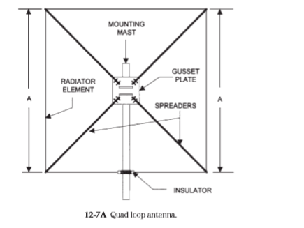
The cubical quad antenna is a one-wavelength square wire loop. It was designed in the mid-1940s at radio station HCJB in Quito, Ecuador. HCJB is a Protestant missionary shortwave radio station with worldwide coverage. The location of the station is at a high altitude. This fact makes the Yagi antenna less useful than it is at lower altitudes. According to the story, HCJB originally used Yagi antennas. These antennas are fed in the center at a current loop, so the ends are high-voltage loops. In the thin air of Quito, the high voltage at the ends caused corona arcing, and that arcing periodically destroyed the tips of the Yagi elements. Station engineer Clarence Moore designed the cubical quad antenna (Fig. 12-7) to solve this problem. Because it is a full-wavelength antenna, each side being a quarter wavelength, and fed at a current loop in the center of one side, the voltage loops occur in the middle of the adjacent sides—and that reduces or eliminates the arcing. The elements can be fed in the center of a horizontal side (Figs. 12-7A and 12-8A), in the center of a vertical side (Fig. 12-8B), or at the corner (Fig. 12-8C).
The antenna shown in Fig. 12-7A is actually a quad loop rather than a cubical quad. Two or more quad loops, only one of which needs to be fed by the coax, are used to make a cubical quad antenna. If only this one element is used, then the antenna will have a figure-8 azimuthal radiation pattern (similar to a dipole). The quad loop antenna is preferred by many people over a dipole for two reasons. First, the quad loop has a smaller “footprint” because it is only a quarter-wavelength on each side (A in Fig. 12-7A). Second, the loop form makes it somewhat less susceptible to local electromagnetic interference (EMI).
The quad loop antenna (and the elements of a cubical quad beam) is mounted to spreaders connected to a square gusset plate. At one time, carpets were wrapped around bamboo stalks, and those could be used for quad antennas. Those days are gone, however, and today it is necessary to buy fiberglass quad spreaders. A number of kits are advertised in ham radio magazines.
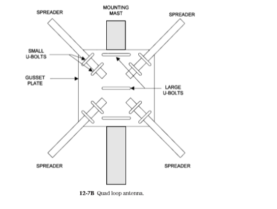
The details for the gusset plate are shown in Fig. 12-7B. The gusset plate is made of a strong insulating material such as fiberglass or 3⁄4-in marine-grade plywood. It is mounted to a support mast using two or three large U bolts (stainless steel to prevent corrosion). The spreaders are mounted to the gusset plate using somewhat smaller U bolts (again, use stainless steel U bolts to prevent corrosion damage).
There is a running controversy regarding how the antenna compares with other beam antennas, particularly the Yagi. Some experts claim that the cubical quad has a gain of about 1.5 to 2 dB higher than a Yagi (with a comparable boom length between the two elements). In addition, some experts claim that the quad has a lower angle of radiation. Most experts agree that the quad seems to work better at low heights above the earth’s surface, but the difference disappears at heights greater than a half-wavelength.
The quad can be used as either a single-element antenna or in the form of a beam. Figure 12-9 shows a pair of elements spaced 0.13 to 0.22 wavelengths apart. One element is the driven element, and it is connected to the coaxial-cable feedline directly. The other element is a reflector, so it is a bit longer than the driven element.
A tuning stub is used to adjust the reflector loop to resonance.
Because the wire is arranged into a square loop, one wavelength long, the actual length varies from the naturally resonant length by about 3 percent. The driven element is about 3 percent longer than the natural resonant point. The overall lengths of the wire elements are
One method for the construction of the quad beam antenna is shown in Fig. 12-10. This particular scheme uses a 12 12-in wooden plate at the center, bamboo (or fiberglass) spreaders, and a wooden (or metal) boom. The construction must be heavy-duty in order to survive wind loads. For this reason, it is probably a better solution to buy a quad kit consisting of the spreaders and the center structural element.
More than one band can be installed on a single set of spreaders. The size of the spreaders is set by the lowest band of operation, so higher frequency bands can be accommodated with shorter loops on the same set of spreaders.
From Joseph P Carr Book " Practical Antenna HandBook"
The counterpoise longwire Antenna
The longwire antenna is an end-fed wire more than 2λ long. It provides considerable gain over a dipole, especially when a very long length can be accommodated. Although 75- to 80-m, or even 40-m longwires are a bit difficult to erect at most locations, they are well within reason at the upper end of the HF spectrum. Low-VHF band operation is also practical. Indeed, I know one fellow who lived in far southwest Virginia as a teenager, and he was able to get his family television reception for very low cost by using a TV longwire (channel 6) on top of his mountain. There are some problems with longwires that are not often mentioned.
Two problems seem to insinuate themselves into the process. First, the Zepp feed is a bit cumbersome (not everyone is enamored of parallel transmission line). Second, how do you go about actually grounding that termination resistor? If it is above ground, then the wire to ground is long, and definitely not at ground potential for RF. If you want to avoid both the straight Zepp feed system employed by most such antennas, as well as the resistor-grounding problem, then you might want to consider the counterpoise longwire antennas shown in Fig. 6-25.
A counterpoise ground is a structure that acts like a ground, but is actually electrically floating above real ground (and it is not connected to ground). A groundplane of radials is sometimes used as a counterpoise ground for vertical antennas that are mounted above actual earth ground. In fact, these antennas are often called ground plane verticals. In those antennas, the array of four (or more) radials from the shield of the coaxial cable are used as an artificial, or counterpoise, ground system. In the counterpoise longwire of Fig. 6-25A, there are two counterpoise grounds (although, for one reason or another, you might elect to use either, but not both).
One counterpoise is at the feedpoint, where it connects to the “cold” side of the transmission line. The parallel line is then routed to an antenna tuning unit (ATU), and from there to the transmitter. The other counterpoise is from the cold end of the termination resistor to the support insulator. This second counterpoise makes it possible to eliminate the earth ground connection, and all the problems that it might entail, especially in the higher end of the HF spectrum, where the wire to ground is of substantial length compared with 1λ of the operating frequency.
A slightly different scheme used to adapt the antenna to coaxial cable is shown in Fig. 6-25B. In this case, the longwire is a resonant type (nonterminated). Normally, one would expect to find this antenna fed with 450-Ω parallel transmission line. But with a λ/4 radial acting as a counterpoise, a 4:1 balun transformer can be used to effect a reasonable match to 75-Ω coaxial cable. The radial is connected to the side of the balun that is also connected to the coaxial cable shield, and the other side of the balun is connected to the radiator element.
From The Book " Practical Antenna Handbook - Joseph P. Carr"
Rhombic Antenna
Rhombic inverted-vee antenna
A variation on the theme is the vertically polarized rhombic of Fig. 6-23. Although sometimes called an inverted vee—not to be confused with the dipole variant of the same name—this antenna is half a rhombic, with the missing half being “mirrored” in the ground (similar to a vertical). The angle at the top of the mast (Φ) is typically ≥ 90°, and 120 to 145° is more common. Each leg (A) should be ≥λ, with the longer lengths being somewhat higher in gain, but harder to install for low frequencies. A requirement for this type of antenna is a very good ground connection. This is often accomplished by routing an underground wire between the terminating resistor ground and the feedpoint ground.
Multiband fan dipole
The basic half-wavelength dipole antenna is a very good performer, especially when cost is a factor. The dipole yields relatively good performance for practically no in
vestment. A standard half-wavelength dipole offers a bidirectional figure-8 pattern on its basic band (i.e., where the length is a half-wavelength), and a four-lobe cloverleaf pattern at frequencies for which the physical length is 3λ/2. Thus, a 40-m halfwavelength dipole produces a bidirectional pattern on 40 m, and a four-lobe cloverleaf pattern on 15 m.
The dipole is not easily multibanded without resorting to traps . One can, however, tie several dipoles to the same center insulator or balun transformer. Figure 6-24 shows three dipoles cut for different bands, operating from a common feedline and balun transformer: A1–A2, B1–B2, and C1–C2. Each of these antennas is a half-wavelength (i.e., Lfeet = 468/FMHz).
There are two points to keep in mind when building this antenna. First, try to keep the ends spread a bit apart, and second, make sure that none of the antennas is cut as a half-wavelength for a band for which another is 3λ/2. For example, if you make A1–A2 cut for 40 m, then don’t cut any of the other three for 15 m. If you do, the feedpoint impedance and the radiation pattern will be affected.
From The Book " Practical Antenna Handbook - by Joseph P. Carr"
Vee-sloper antenna
The vee-sloper antenna is shown in Fig. 6-22. It is related to the vee beam (covered in Chap. 9), but it is built like a sloper (i.e., with the feed end of the antenna high above ground). The supporting mast height should be about half (to three-fourths) of the length of either antenna leg. The legs are sloped downward to terminating
resistors at ground level. Each wire should be longer than 1λat the lowest operating frequency. The terminating resistors should be on the order of 270 Ω(about one-half of the characteristic impedance of the antenna), with a power rating capable of dissipating one-third of the transmitter power. Like other terminating resistors, these should be noninductive (carbon composition or metal film). The advantage of this form of antenna over the vee beam is that it is vertically polarized, and the resistors are close to the earth, so they are easily grounded.
From The Book : "Practical Antenna Handbook - Joseph P. Carr"
The TCFTFD dipole
The tilted, center-fed, terminated, folded dipole(TCFTFD, also called the T2FD or TTFD) is an answer to both the noise pickup and length problems that sometimes affect other antennas. For example, a random-length wire, even with antenna tuner, will pick up considerable amounts of noise. A dipole for 40 m is 66 ft long.
This antenna was first described publicly in 1949 by Navy Captain C. L. Countryman, although the U.S. Navy tested it for a long period in California during World War II. The TCFTFD can offer claimed gains of 4 to 6 dB over a dipole, depending on the frequency and design, although 1 to 3 dB is probably closer to the mark in practice, and less than 1 dB will be obtained at some frequencies within its range (especially where the resistor has to absorb a substantial portion of the RF power). The main attraction of the TCFTFD is not its gain, but rather its broad bandedness.
In addition, the TCFTFD can also be used at higher frequencies than its design frequency. Some sources claim that the TCFTFD can be used over a 5 or 6:1 frequency range, although my own observations are that 4:1 is more likely. Nonetheless, a 40-m antenna will work over a range of 7000 to 25,000 kHz, with at least some decent performance up into the 11-m Citizen’s Band (27,000 kHz).
The basic TCFTFD (Fig. 6-21) resembles a folded dipole in that it has two parallel conductors of length L, spaced a distance W apart, and shorted together at the
ends. The feedpoint is the middle of one conductor, where a 4:1 balun coil and 75-Ω coaxial-cable transmission line to the transceiver are used. A noninductive, 390-Ω resistor is placed in the center of the other conductor. This resistor can be a carbon-composition (or metal-film) resistor, but it must not be a wirewound resistor or any other form that has appreciable inductance. The resistor must be able to dissipate about one-third of the applied RF power. The TCFTFD can be built from ordinary no.14 stranded antenna wire.
For a TCFTFD antenna covering 40 through 11 m, the spread between the conductors should be 191⁄2 in, while the length L is 27 ft. Note that length L includes one-half of the 19-in spread because it is measured from the center of the antenna element to the center of the end supports.
The TCFTFD is a sloping antenna, with the lower support being about 6 ft off the ground. The height of the upper support depends on the overall length of the antenna. For a 40-m design, the height is on the order of 50 ft.
The parallel wires are kept apart by spreaders. At least one commercial TCFTFD antenna uses PVC spreaders, while others use ceramic. You can use wooden dowels of between 1-in and 5⁄8-in diameter; of course, a coating of varnish (or urethane spray) is recommended for weather protection. Drill two holes, of a size sufficient to pass the wire, that are the dimension W apart (19 in for 40 m). Once the spreaders are in place, take about a foot of spare antenna wire and make jumpers to hold the dowels in place. The jumper is wrapped around the antenna wire on either side of the dowel, and then soldered.
The two end supports can be made of 1 × 2 in wood treated with varnish or urethane spray. The wire is passed through screw eyes fastened to the supports. A support rope is passed through two holes on either end of the 1 × 2 and then tied off at an end insulator.
The TCFTFD antenna is noticeably quieter than the random-length wire antenna, and somewhat quieter than the half-wavelength dipole. When the tilt angle is around 30°, the pattern is close to omnidirectional. Although a little harder to build than dipoles, it offers some advantages that ought not to be overlooked. These dimensions will suffice when the “bottom end” frequency is the 40-m band, and it will work well on higher bands.
From The Book " Practical Antenna Handbook " Joseph P. Carr
Subscribe to:
Comments (Atom)